Rollable heating component for ground or wall

A heating component, roll-type technology, applied in the field of architectural decoration, can solve the problems of low thermal efficiency, poor comfort, complex structure, etc.

Active Publication Date: 2014-01-29
淮南市启迪电子有限公司
View PDF10 Cites 5 Cited by
  • Summary
  • Abstract
  • Description
  • Claims
  • Application Information

AI Technical Summary

Problems solved by technology

The water supply temperature of the radiator group is usually 70-85°C. The disadvantages are: high energy consumption, low thermal efficiency, uneven indoor temperature, and higher temperature above than below, that is, the indoor surface temperature is lower, so the comfort is better. Difference
It can be seen from this that the heating device needs to lay a wooden floor 15 on its covering layer 12. The structure of this floor heating method is relatively complicated, and there are many construction procedures, and it is easy to cause damage to the heating element 11 during construction.

Method used


Image

  • Rollable heating component for ground or wall
  • Rollable heating component for ground or wall
  • Rollable heating component for ground or wall

Examples


Embodiment 1

[0091] (Example 1, heating components for the ground or wall)

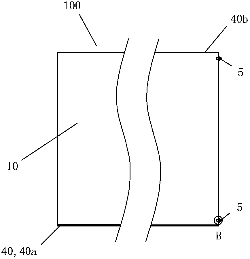
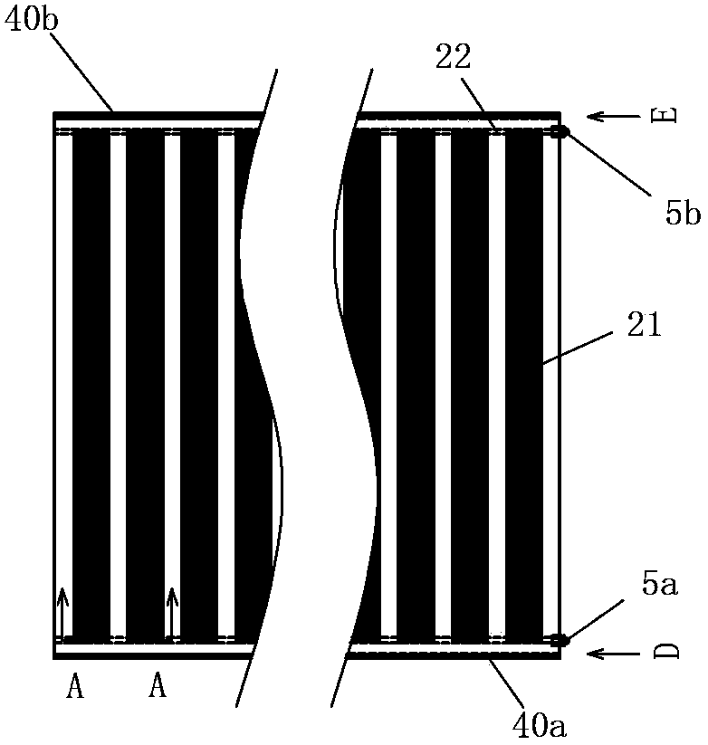
[0092] See figure 1 and image 3 , the heating component 100 of the present invention includes a heating board 10 , a fastener 40 and a socket 5 . The buckle 40 is composed of a front buckle 40 a located at the front of the heating board 10 and a rear buckle 40 b located at the rear of the heating board 10 . The front buckle 40a is the position where the rear buckle 40b of the heating element 100 of the same structure adjacent to the front side is connected and matched with each other; The front buckle parts 40a of the heat generating component 100 of the structure are connected and matched with each other. The socket 5 is composed of a front socket 5a (right front in this embodiment) and a rear socket 5b (right rear in this embodiment) on the same side as the left and right sides of the heating plate 10 .

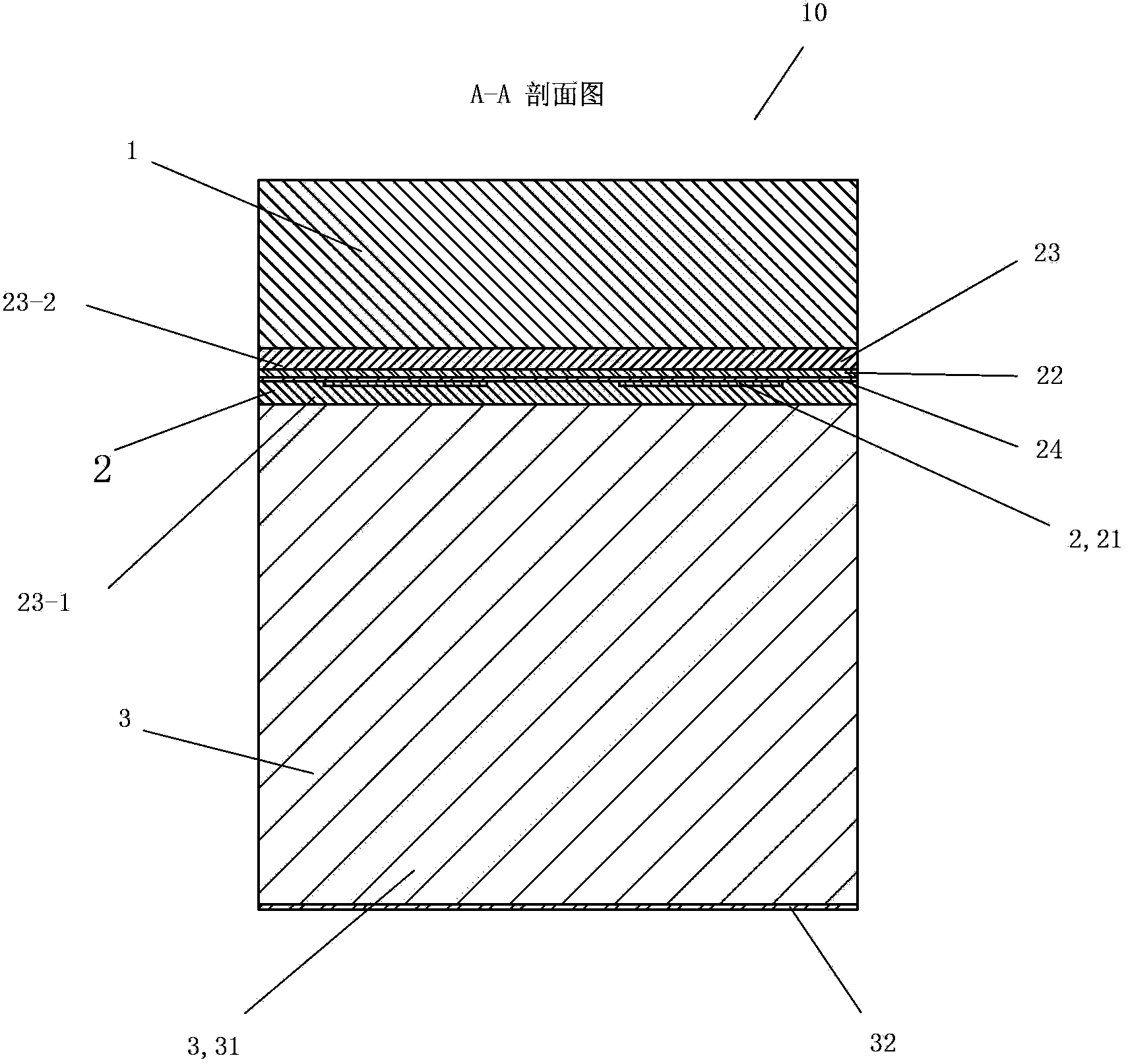
[0093] See Figure 1 to Figure 3 , The heating plate 10 includes a decorative surface layer 1 , a heat...

Embodiment 2

[0131] (Example 2, heating components for the ground or wall)

[0132] See Figure 23 to Figure 26 , The rest of this embodiment is the same as that of Embodiment 1, except that the lower clamping device 54a of the bottom plate 54 of the socket 5 is a bead 54a-2. There are 1 to 4 bead 54a-2 (there are 2 in this embodiment), and the structural shape of each bead 54a-2 is the same. on the triangle.

[0133] The upper clamping device 55b of the pressing plate 55 of the socket 5 is a pressing bar 55b-2. There are 1 to 4 bead 55b-2 (there are 2 in this embodiment), and the structural shape of each bead 55b-2 is the same. Downside down triangle.


PUM

PropertyMeasurementUnit
Lengthaaaaaaaaaa
Lengthaaaaaaaaaa
Thicknessaaaaaaaaaa

Abstract

The invention discloses a rollable heating component for a ground or a wall. The rollable heating component comprises a heating plate and sockets, and the heating plate comprises a bottom layer. The rollable heating component is characterized in that the heating plate further comprises a decorative surface layer and a heating layer, and the decorative surface layer, the heating layer and the bottom layer are sequentially arranged from top to bottom. The decorative surface layer is a PVC coiled material floor layer, the decorative surface layer and the heating layer are fixedly bonded together, and the heating layer and the bottom layer are fixedly bonded together. The upper surface of the decorative surface layer is exposed when the decorative surface layer is used. The heating layer of the heating plate is an electrothermal film. The number of the sockets is two, the two sockets are divided into a front socket and a back socket according to different front-and-back positions of the sockets, and the front socket and the back socket are electrically connected with the corresponding electrodes of the electrothermal film of the heating plate respectively. The sockets are electrically connected with a power system through power supply lines, and the heating plate emits heat for heating after the heating plate is powered on.

Description

technical field [0001] The invention relates to a product in the field of architectural decoration, in particular to a rollable heating element used on the ground or wall. Background technique [0002] The traditional heating in northern my country adopts centralized heating, and the pipes in the room are connected to the radiator to heat and heat by convection. The convection of indoor hot air can easily cause dust to float and the air to be dry. The water supply temperature of the radiator group is usually 70-85°C. The disadvantages are: high energy consumption, low thermal efficiency, uneven indoor temperature, and higher temperature above than below, that is, the indoor surface temperature is lower, so the comfort is better. Difference. In addition, the radiator group also needs to occupy a certain space, and affects the appearance. [0003] Since the heat source of floor heating comes from the ground, a gradually decreasing temperature gradient is formed in the room f...

Claims


Application Information

Patent Timeline
IPC IPC(8): F24D13/02H05B3/36
CPCY02B30/00
Inventor 葛林葛鑫琰
Owner 淮南市启迪电子有限公司
Why Eureka
Try Eureka