Eureka AIR delivers breakthrough ideas for toughest innovation challenges, trusted by R&D personnel around the world.

Blade structure of wind wheel for vertical shaft wind-driven generator

A technology of blade structure and vertical axis, applied in the field of blade structure of vertical axis wind turbine wind turbine, can solve the problem that the wind rotor has not been completely solved, and achieve the effect of light weight, simple combined processing and high efficiency

Active Publication Date: 2011-08-10
NAT WIND ENERGY
View PDF5 Cites 9 Cited by
  • Summary
  • Abstract
  • Description
  • Claims
  • Application Information

AI Technical Summary

Problems solved by technology

Therefore, many problems of the above-mentioned horizontal axis wind turbine rotor have not been completely solved

Method used


Image

  • Blade structure of wind wheel for vertical shaft wind-driven generator
  • Blade structure of wind wheel for vertical shaft wind-driven generator
  • Blade structure of wind wheel for vertical shaft wind-driven generator

Examples


Embodiment Construction

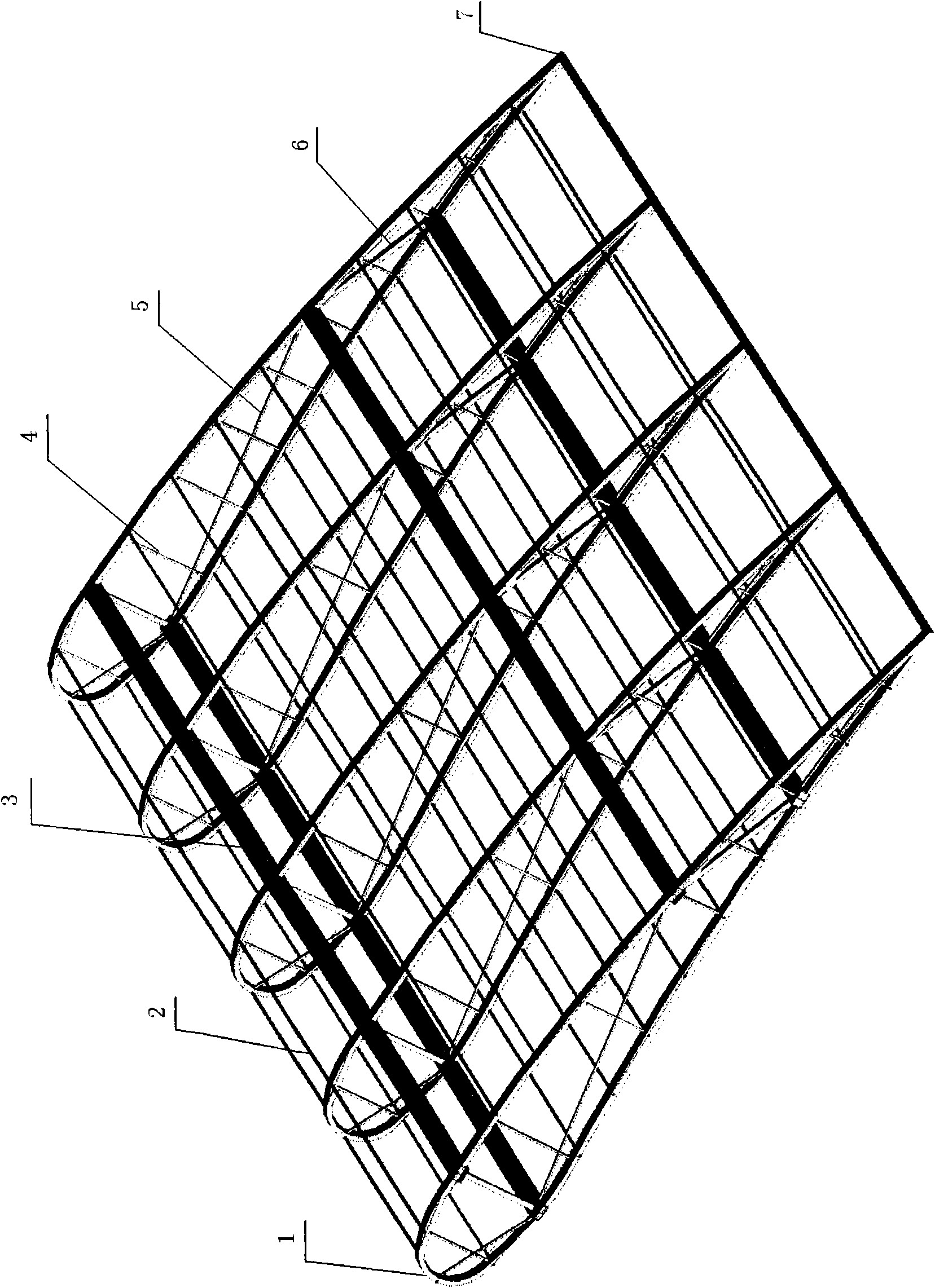
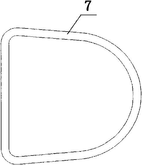
[0033] Such as figure 1 As shown, the blade of the vertical axis wind turbine rotor provided by the present invention includes a skeleton forming the shape of the blade and a skin (not shown) fixed outside the skeleton, and the shape of the blade is a vertical columnar body , its horizontal section is the cross-sectional shape of the aircraft wing, that is, relative to the rotation axis 03 of the wind rotor (see Figure 6 , 7 ), the outer surface of the blade 01 facing outward is a streamlined arc surface, and the smooth transition between the outer surface and the opposite inner surface forms a larger windward end, that is, the head of the blade and a smaller tail.

[0034] Relative to the vertical axis of the wind rotor shaft 03, the distance between the outer surface and the inner surface of the cylinder basically gradually decreases from the head to the tail; in the vertical direction of the blade, each horizontal The cross-sectional size and shape are the same.

[0035...


PUM


Abstract

The invention provides a blade of a wind wheel for a vertical shaft wind-driven generator. The blade comprises a blade-shaped framework and a shell which is fixed at the outer surface of the framework, wherein the shape of the blade is a vertical column, and the horizontal cross section of the vertical column is in the shape of the section of the airfoil of an airplane, i.e., the outward outer side surface of the blade is a streamline-shaped arc surface; and the smooth transition of the outer side surface and the opposite inner side surface forms a larger windward end, namely the head part and smaller tail of the blade. Because of the stream-shaped form and specific framework structure of the blade provided by the invention, the blade has the advantages of light weight, high intensity andrigidity, simplicity in combination and manufacturing and high molding accuracy.

Description

technical field [0001] The invention belongs to the technical field of wind power generators, and provides a component of a vertical axis wind power generator, in particular a blade structure of a wind wheel of a vertical axis wind power generator. Background technique [0002] In the prior art, most of the wind power generators are horizontal shaft generators, the main shaft is set horizontally, and the wind wheel is set on it. , It is easy to deform and generate resonance under wind force, and it is easy to break under wind pressure, which has the problem of poor wind resistance, and the resonance during rotation can cause the problem of low power generation. Due to the above-mentioned problems of this type of wind rotor blades, and the current wind turbines are developing toward large-scale and high-power, with the increase of the diameter of the wind rotor, the damage rate of the blades is higher and the service life is shorter. The development of power generation has a...

Claims


Application Information

Patent Timeline
IPC IPC(8): F03D3/06
CPCF05B2250/231F03D3/062F05B2240/214Y02E10/721Y02E10/74Y02E10/72Y02P70/50
Inventor 蒋大龙盛明凡许金泉
Owner NAT WIND ENERGY
Why Eureka
Eureka Blog
Learn More