
Floating type servo valve

By adopting a floating design and a displacement amplification mechanism in the servo valve, the problems of limited output flow and high friction of the existing servo valve are solved, high sensitivity and dynamic and static performance are improved, and it can adapt to the needs of different equipment interfaces.

Active Publication Date: 2011-08-10
HANGZHOU XZB TECH CO LTD
View PDF7 Cites 4 Cited by
  • Summary
  • Abstract
  • Description
  • Claims
  • Application Information

AI Technical Summary

Problems solved by technology

[0004] First, due to the limitation of the performance of the magnetic material itself and the requirement of output linearity, the rotation angle θ of the electric drive armature mechanism is small, so the output flow of the power stage is also limited accordingly
[0005] Second, the connection between the electric drive armature mechanism and the pilot stage control mechanism is a rigid connection, and the deflection force generated by the assembly error is applied to the pilot stage shaft, and the deflection force is difficult to eliminate, which will make the pilot stage shaft and the valve There is a large friction force between the body shaft holes, which makes the performance indicators of the servo valve such as hysteresis, sensitivity, zero dead zone and nonlinear error worse.
[0006] Third, when the servo valve is working, the rotating shaft of the pilot stage is affected by the return pressure of the valve inner cavity, and an upward force will be generated on the rotating shaft. This force will cause the pilot stage to generate greater friction, so that the servo valve Decreased dynamic and static performance
[0007] Fourth, the two pistons of the power stage are fitted on the inner cavity of the valve body. Under the pressure of the piston cavity, the piston and the inner cavity wall of the valve body will generate a large friction force, which will easily make the movement of the power stage jammed and inflexible. Affect the dynamic and static performance of the servo valve

Method used


Image

  • Floating type servo valve
  • Floating type servo valve
  • Floating type servo valve

Examples


Embodiment Construction

[0035] The specific embodiment of the present invention will be further described below in conjunction with accompanying drawing:

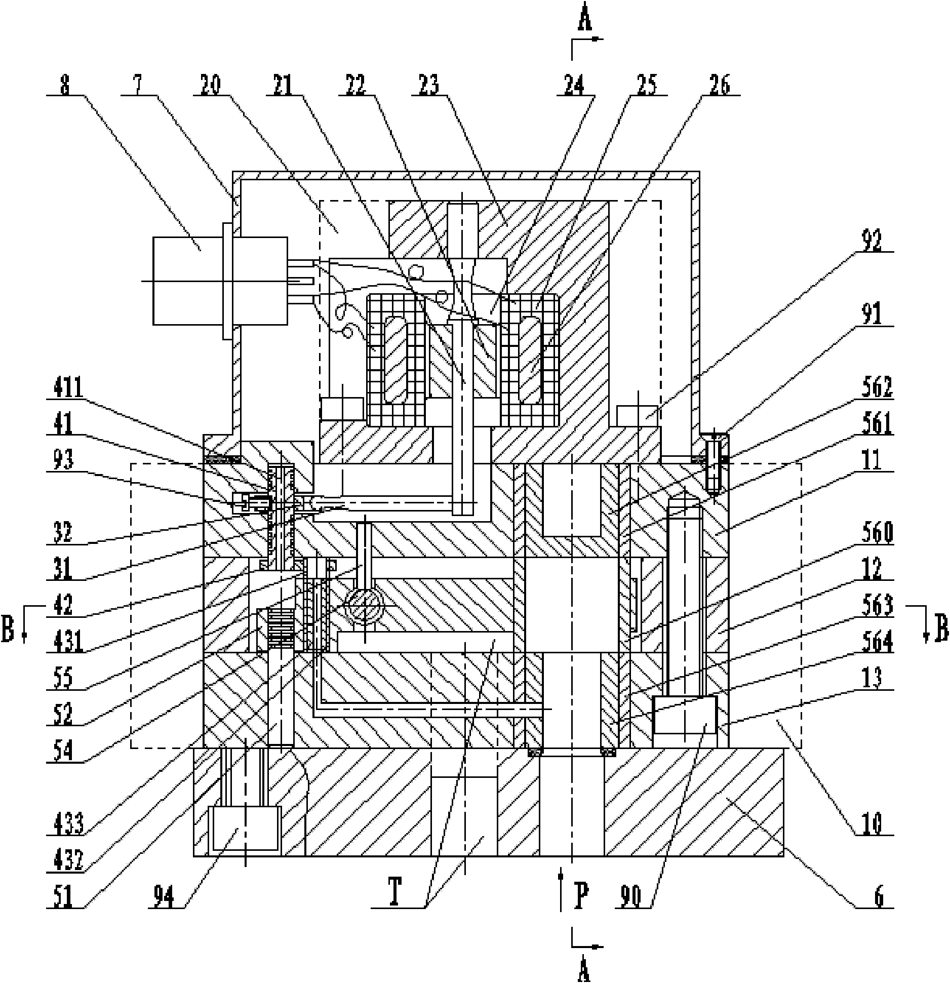
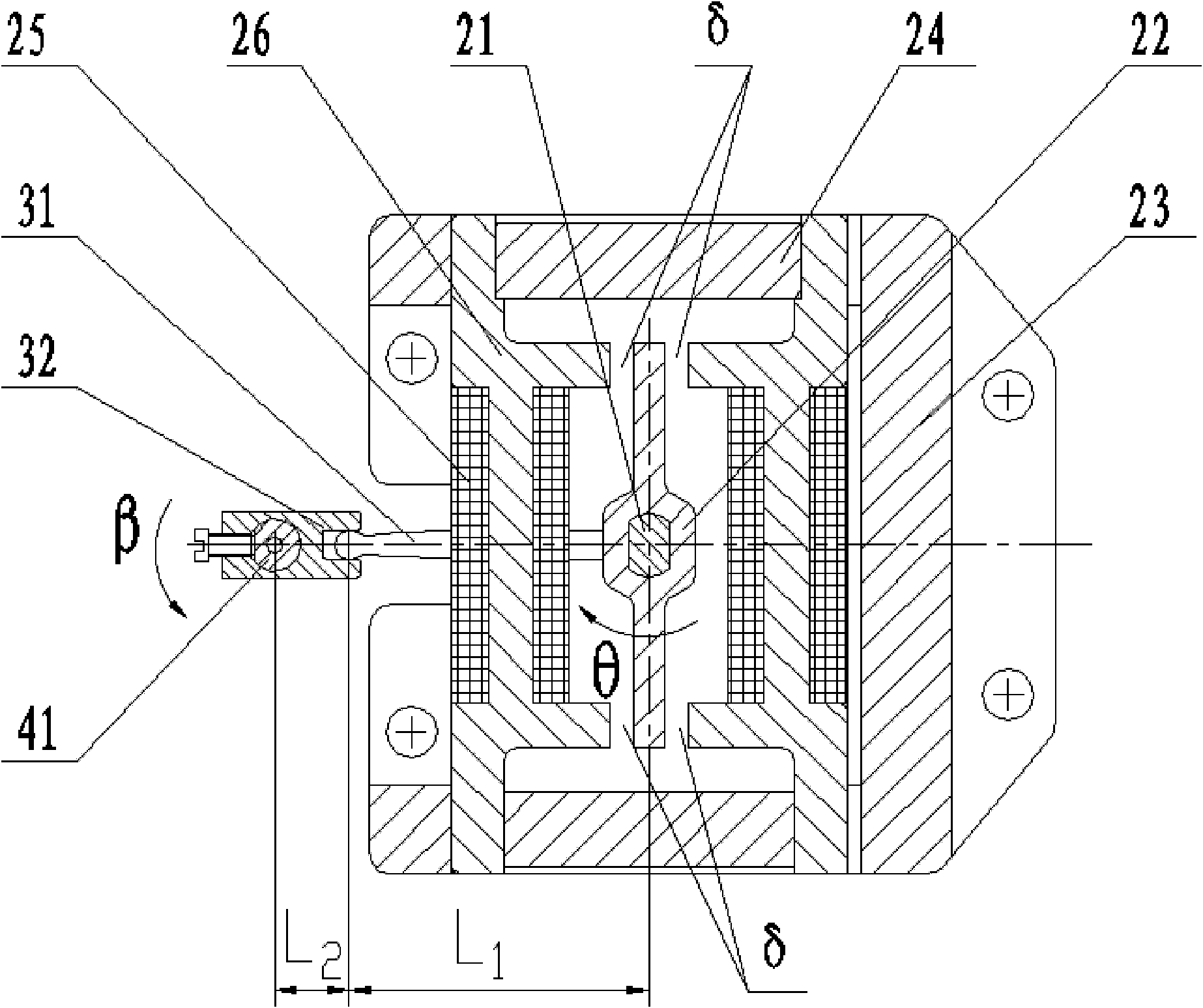
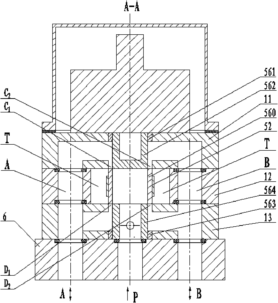
[0036] Such as Figure 1 to Figure 7 As shown, the floating servo valve of the present invention is mainly composed of a valve body 10, a torque motor 20, a pilot stage control mechanism and a power stage control mechanism arranged in the inner cavity of the valve body.

[0037] The valve body 10 includes an upper valve block 11 , a middle partition 12 and a lower valve block 13 , which are stacked in sequence and fastened by screws 90 . The upper and lower planes of the middle partition 12 are parallel to each other, and the middle partition 12 is provided with two flow holes A and B, and the upper valve block 11 and the lower valve block 13 are respectively provided with flow holes corresponding to the flow holes A and B. The holes are arranged in the corresponding orifices of the three to communicate with each other respectively. The outer co...


PUM


Abstract

The invention belongs to the technical field of valves, in particular relates to a floating type servo valve for fluid control. The floating type servo valve comprises a valve body, a moment motor, a pilot-level control mechanism and a power-level control mechanism, wherein an upper valve block, a vertical aividing partition and a lower valve block of the valve body are overlapped through a fastening member, and a torsional bar spring of the moment motor passes through the center of an armature and is fixed on the valve body through a bracket; and a pilot-level rotating shaft and a power-level rotating shaft are arranged on the same center line, the pilot-level rotating shaft is matched with a rotating shaft hole of the upper valve block, and the power-level rotating shaft is matched with a rotating shaft hole of the lower valve block. The servo valve also comprises a displacement amplifying mechanism consisting of a shifting fork and a shifting bar, the rotating center of the shifting fork is arranged on the axes of the pilot-level rotating shaft, the rotating center of the shifting bar is arranged on the axes of the torsional bar spring, one end of the shifting bar is connected with the lower end of the torsional bar spring of the moment motor and the other end is in sliding transmission connection with the shifting fork. The floating type servo valve has the advantages of adjustable power-level output flow, better movable and static performances, small friction, flexibility in movement, and the like.

Description

technical field [0001] The invention belongs to the technical field of valves, in particular to a floating servo valve for fluid control. Background technique [0002] The electronically controlled fluid servo valve is an automatic control valve. Its function is to amplify low-power electrical signals into high-power fluid energy output, so as to realize precise control of physical quantities such as the position, speed, and force of the load. In some automation industries that require fast response, high control precision, and high output power, servo control systems must be used. Servo valves are the core components of servo control systems, and their performance has a decisive effect on the entire system. Therefore, The development of high-performance servo valves is of great significance to the development of the automation industry. [0003] Chinese patent ZL02252246.8 discloses a two-stage ring servo valve, which is composed of an electrically driven armature mechanis...

Claims


Application Information

Patent Timeline
Patent Type & Authority Applications(China)
IPC IPC(8): F15B13/02
CPCF16K31/0682F15B13/043F15B13/02F16K31/10Y10T137/7761
Inventor 董华
Owner HANGZHOU XZB TECH CO LTD
Learn More