Optical device using negative goos-hanchen shift

An optical element and displacement technology, applied in the field of optical elements, can solve the problems of complex fabrication process of photonic crystal waveguides, difficulty in readjusting the retardation characteristics of optical delay elements, etc.

Inactive Publication Date: 2011-08-10
财团法人中央大学校产学协力团
View PDF1 Cites 4 Cited by
  • Summary
  • Abstract
  • Description
  • Claims
  • Application Information

AI Technical Summary

Problems solved by technology

However, photonic crystal waveguides require very complex fabrication processes
Moreover, once

Method used


Image

  • Optical device using negative goos-hanchen shift
  • Optical device using negative goos-hanchen shift
  • Optical device using negative goos-hanchen shift

Examples


Embodiment Construction

[0031] The present invention relates to an optical element utilizing negative Goose-Hanchen shift. Before explaining the optical element, the Goose-Hanchen shift will be explained.

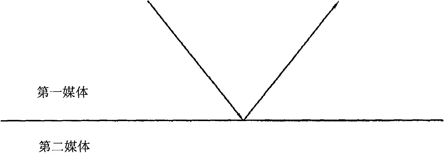
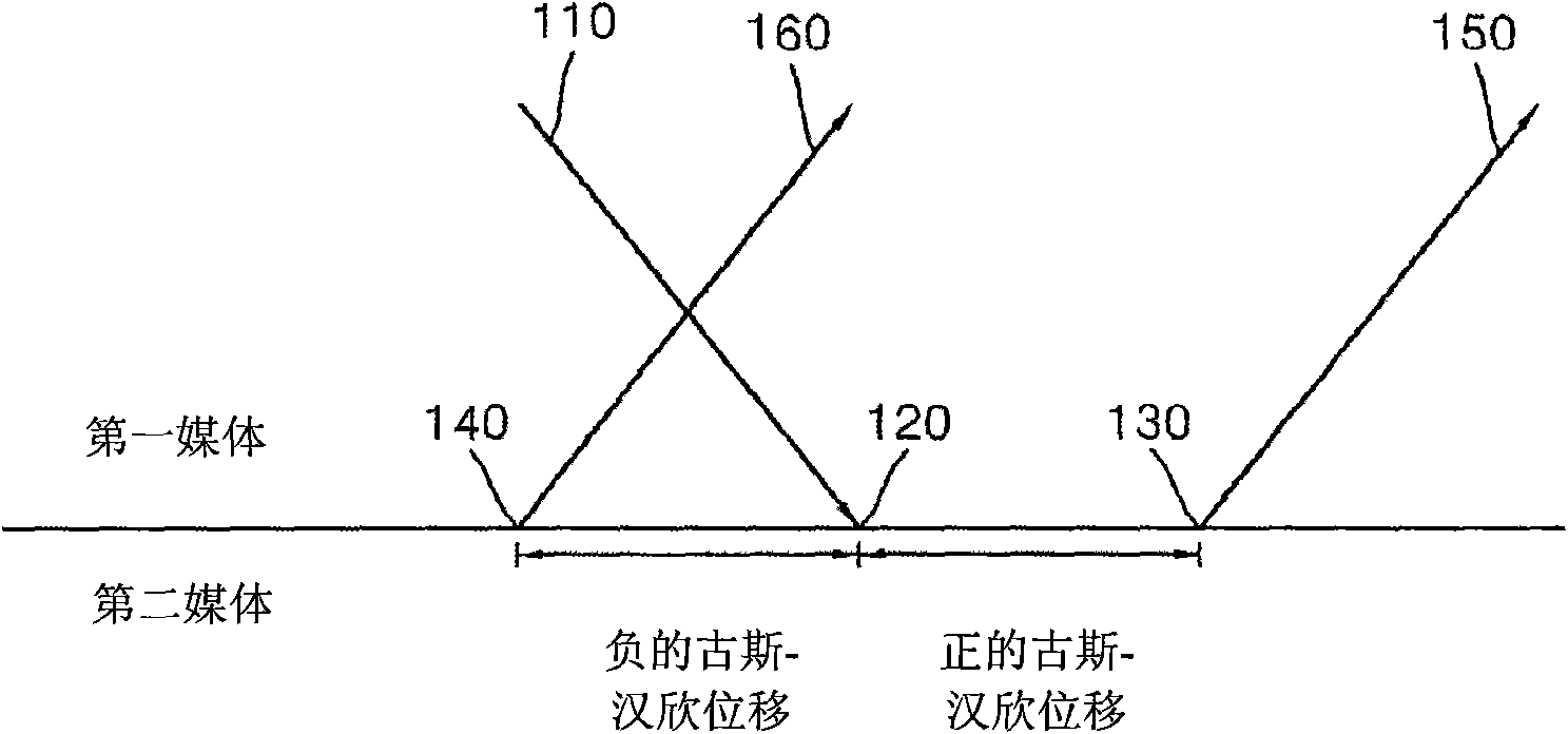
[0032] Figure 1A and Figure 1B is the graph used to explain the Goos-Hanchen shift.

[0033] Such as Figure 1A As shown, when light propagating through a first medium encounters a second medium having a different refractive index than the first medium, the light is reflected from the interface between the first medium and the second medium. Here, the point at which the incident light is reflected may not correspond to the point at which the incident light encounters the interface between the first medium and the second medium.

[0034] More specifically, as Figure 1B As shown, the point where the incident light 110 is reflected may be located more forward or rearward than the light incident point 120 where the incident light encounters the interface between the first medium and the second m...


PUM


Abstract

Provided is an optical device delaying light by using negative Goos-Hanchen shift. The optical device includes an optical waveguide adapted to guide and emit an incident light, a first reflection layer disposed at one side of the optical waveguide, and a second reflection layer disposed at the other side of the optical waveguide. At least one of the first and the second reflection layers is made of a material having characteristics of negative Goos-Hanchen shift.

Description

technical field [0001] The present invention relates to an optical element, in particular to an optical element capable of delaying light by using a negative Goos-Hanchen shift. Background technique [0002] With the development of computers and information appliances, the amount of information is increasing exponentially. As a result, information has long been glutted by rapidly multiplying beyond the current rate of development of various technologies (eg, electrical communication networks, computers, etc.). For this reason, there is a need for an improved communication technique for processing more information more quickly. Unlike electromagnetic waves, light can perform parallel information processing because it is not easily disturbed by electromagnetic waves. Technologies are currently being developed related to optical computers and optical networks that use optical components that are even faster than electronic components. In addition, research on various optical...

Claims


Application Information

Patent Timeline
IPC IPC(8): G02F1/035G02F1/03
CPCG02F1/035G02B5/008G02B6/122G02B6/124G02B6/2861G02B6/1226G02F1/03G02B2006/12107G02B6/12B82Y20/00
Inventor 崔永完吴锦润金斗根金弘升
Owner 财团法人中央大学校产学协力团
Why Eureka
Try Eureka