
Thermal control interface coatings and pigments

a technology of thermal control interface and pigment, applied in the direction of mirrors, thin material processing, instruments, etc., can solve the problems of high cost of the combined electrochemical/chemical oxidation process to obtain the desired surface, inability to select the visible color or appearance of the composite structure, and insufficient radiation control properties of organic paints for some applications, etc., to achieve low chroma and high reflectivity

Inactive Publication Date: 2006-02-02
JDS UNIPHASE CORP +1
View PDF32 Cites 146 Cited by
  • Summary
  • Abstract
  • Description
  • Claims
  • Application Information

AI Technical Summary

Benefits of technology

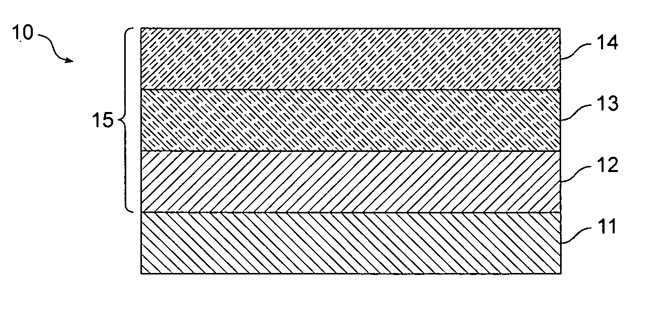
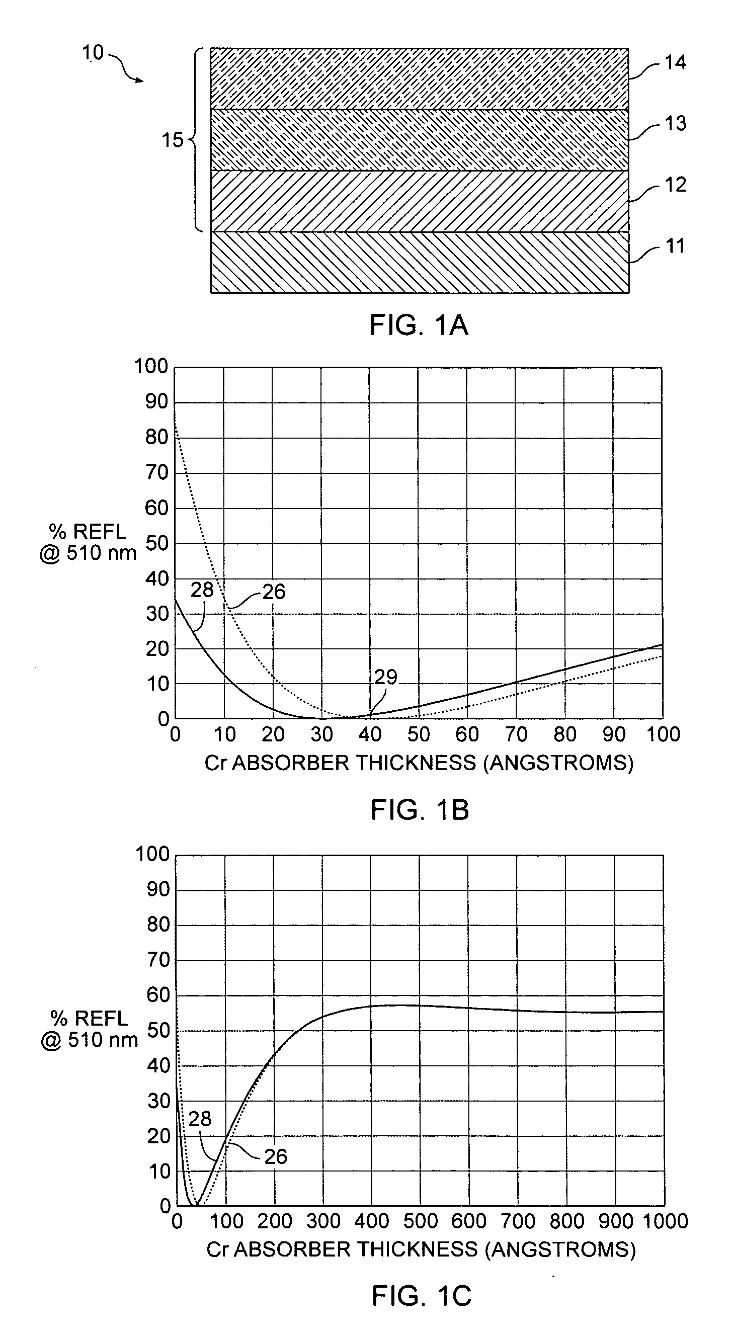
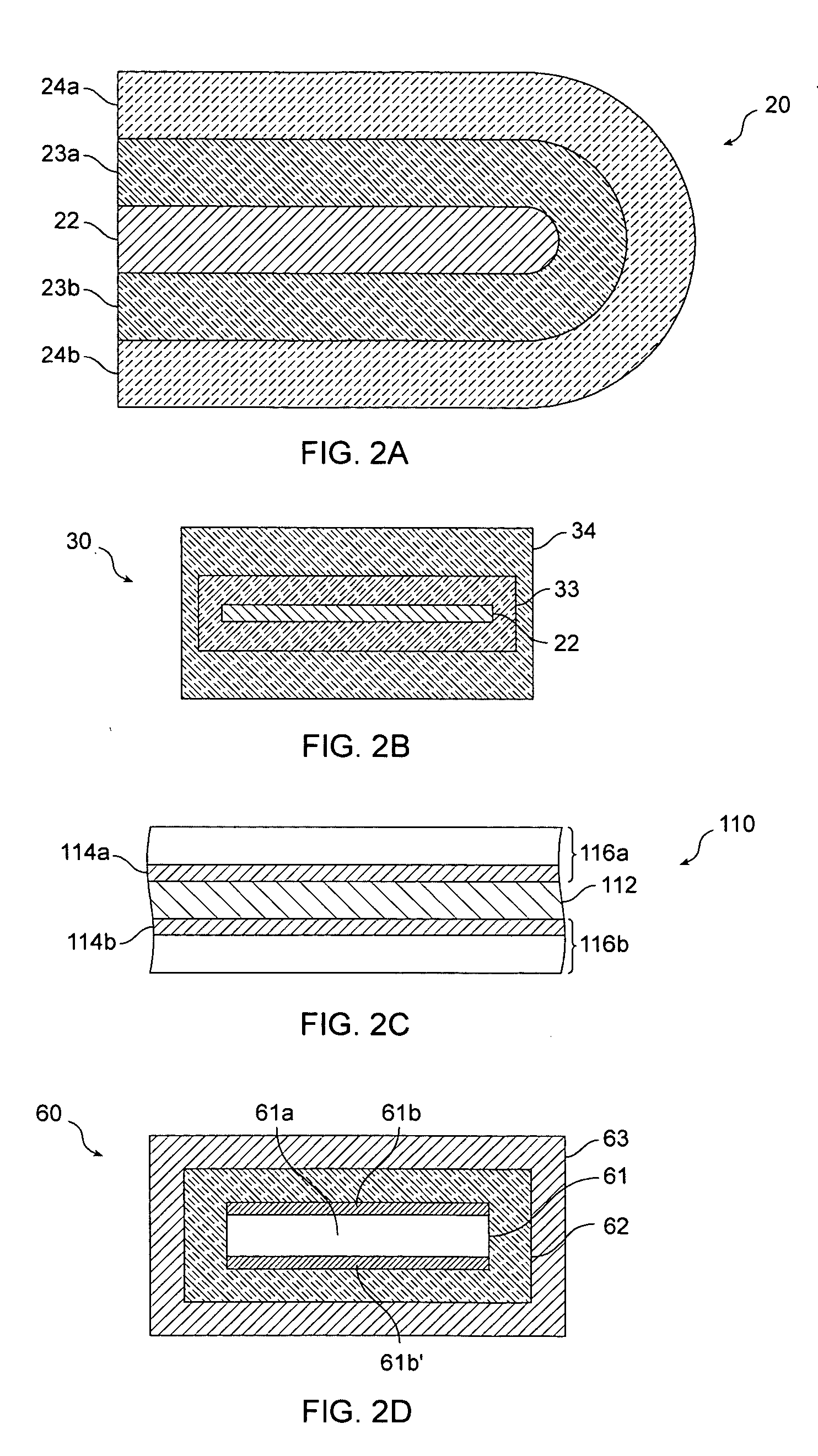
The present invention provides optical interference structures that appear dark or have low chroma in the visible portion of the spectrum and relatively high reflectivity in the infra-red portion of the spectrum. These structures can be used in pigments, such as by forming the optical interference structure on one or both sides of a pigment flake, or forming the structures on a roll of polymer film, and then separating and processing the deposited film structure into pigment flakes. In other embodiments, the optical interference structures are deposited onto a substrate, such as a sheet of foil, that is then attached to an object, or directly onto an object, such as a panel. The foil or object can be reflective and serve as the reflector in the resulting interference structure.

Problems solved by technology

One objection to this method is the high cost of the combined electrochemical / chemical oxidation process to obtain the desired surface.
Another disadvantage is that one cannot select the visible color or appearance of the composite structure, which is the color of cupric oxide.
However, organic-based paints typically release volatile organic compounds, which may be controlled or even prohibited in some areas because of environmental concerns.
Further, such organic paints may not provide sufficient radiation control properties for some applications.
Unfortunately, the pigments can react chemically with the silicate binders in some instances to form pigment silicate salts or complexes.
These compounds alter the properties of absorptance and emittance of the coating to such an extent that the performance of the coating may degrade to an unacceptable level.
Not all semiconductor pigments are useful, as those having a high refractive index and thus a high surface reflection coefficient give rise to unacceptable reflection losses.
Since thermal and photochemical stability is required of the semiconductor, organic dyes would not be very useful and the preferred semiconductors are, therefore, the inorganic pigments already enumerated.
Such thermal control surfaces have undesirable visual appearances for many applications because the broadband reflectors are very bright or metallic in appearance, while selective absorbers have a black appearance in the visible.
This high solar absorption resulted in high surface temperatures that increase cooling requirements and more importantly increased infrared radiation.
However, this method increases electrical power requirements aboard ship as well as adding parasitic weight and volume to equipment aboard the ship.
Like traditional military paints, it utilizes some fraction of visually absorptive pigments, that do not have wavelength specific or optimized infrared properties; their reflectance tends to be constant over different wavelength bands, which compromises its infrared performance.
This often detracts from the IR performance of the coating.
Attempts to achieve other visual colors resulted in some compromise of the thermal control properties

Method used


Image

  • Thermal control interface coatings and pigments
  • Thermal control interface coatings and pigments
  • Thermal control interface coatings and pigments

Examples


Embodiment Construction

[0042] The present invention relates to optical thin film structures that provide low perceived color and relatively high IR reflectivity. Embodiments of the invention may be embodied as pigment flakes for use in paints, inks, plastic sheets (films), plastic objects, and powder coatings, as foils that are attached to objects, or coatings that are formed directly on objects. In some embodiments, the optical thin film structures appear very dark or even black. Objects coated with pigments, foils, or coatings according to these embodiments of the invention have low perceived color because of the low lightness, even though the measured chroma may be fairly high. In other embodiments, a pigment, foil, or coating appears gray, which may have high lightness in combination with relatively low chroma. In yet other embodiments, the optical thin film structures can be selected to provide a low level of color. Typically, such optical thin film structures exhibit little goniometric color shiftin...


PUM


Abstract

The invention provides an optical structure with low chroma and brightness in the visible region and low emissivity in the infrared region. The optical structure includes an interference structure having an infrared reflective layer and an infrared absorbing thin film layer. These layers are in turn separated by a thin film spacer of a dielectric or semiconductor material. The reflectivity and transmission of the layers are selectively controlled through the thickness of the layers such that the visual reflectivity and color is independent of the infrared properties of the absorber and reflector layers.

Description

CROSS REFERENCE TO RELATED APPLICATIONS [0001] Not applicable. STATEMENT REGARDING FEDERALLY SPONSORED RESEARCH OR DEVELOPMENT [0002] Not applicable REFERENCE TO SEQUENCE LISTING [0003] Not applicable BACKGROUND OF THE INVENTION [0004] This invention relates to partially reflective coatings useful for controlling thermal radiation, that is infrared reflective coatings that that have selectively controlled optical properties in visual wavelengths permitting a wide variation in perceived color and brightness having optimal infrared optical properties. [0005] Various methods have been used to achieve thermal radiation control of objects by selectively controlling the object's reflectivity to infrared radiation. Methods generally involve either applying a coating to an object or forming its outer surface of a material having high infrared reflectivity. Thermal radiation controlled objects and surfaces have a number of uses, among which are solar collector absorber panels, space vehicle ...

Claims


Application Information

Patent Timeline
Patent Type & Authority Applications(United States)
IPC IPC(8): G02B5/08G02B7/182
CPCG02B5/0816G02B5/0825Y10T428/2993G02B5/281Y10T428/2991G02B5/0858
Inventor COOMBS, PAUL G.MARKANTES, CHARLES T.PHILLIPS, ROGER W.
Owner JDS UNIPHASE CORP
Learn More