Luminous element, and display device and lighting device using it

a light-emitting element and light-emitting element technology, applied in the field of self-luminous light-emitting elements, can solve the problems of limited luminescence efficiency of light-emitting elements, insufficient luminance of elements, and difficulty in forming reflective films on light-emitting elements which correspond to units of pixels, so as to improve the efficiency of external extraction

Inactive Publication Date: 2004-01-22
JOLED INC
View PDF0 Cites 135 Cited by
  • Summary
  • Abstract
  • Description
  • Claims
  • Application Information

AI Technical Summary

Benefits of technology

0142] It is to be noted, however, that the aerogel layer is not essential; similar advantageous effects can be obtained even without the aerogel layer.
0143] The present embodiment corresponds to the foregoing fifth aspect. A light-emitting element of the present embodiment comprises an aerogel layer with a refractive index of approximately 1, and the distance between the surface of the light-emitting region facing the aerogel layer side and the surface of the aerogel layer facing the light-emitting region side, is limited to 50% or less, and preferably 30% or less, and more preferably 20% or less, and most preferably 10% or less of the peak wavelength of light. In addition, the layered structure includes a reflective layer for reflecting light emitted from the light-emitting region, and a light-scattering portion is present in a part of the reflective layer. When the construction is made to satisfy the both conditions as described above, most of the light emitted from the light-emitting region can be extracted outside the element without undergoing total reflection. Even if the light is totally reflected, because the incident angle of the light on the light-extracting surface becomes less than the critical angle due to the presence of the light-scattering portion, the light is extracted outside the element, re

Problems solved by technology

However, this element did not achieve sufficient luminance even when a high voltage was applied to the element, and thus required further improvement in luminescence efficiency.
One of the factors contributing to the limited luminescence efficiency of these light-emitting elements is the external extraction efficiency of light emitted from the light-emitting layer (external extraction efficiency).
However, in the case, for example, of a so-called dot matrix display in which very small light-emitting e

Method used


Image

  • Luminous element, and display device and lighting device using it
  • Luminous element, and display device and lighting device using it
  • Luminous element, and display device and lighting device using it

Examples


embodiment 1

[0100] Embodiment 1

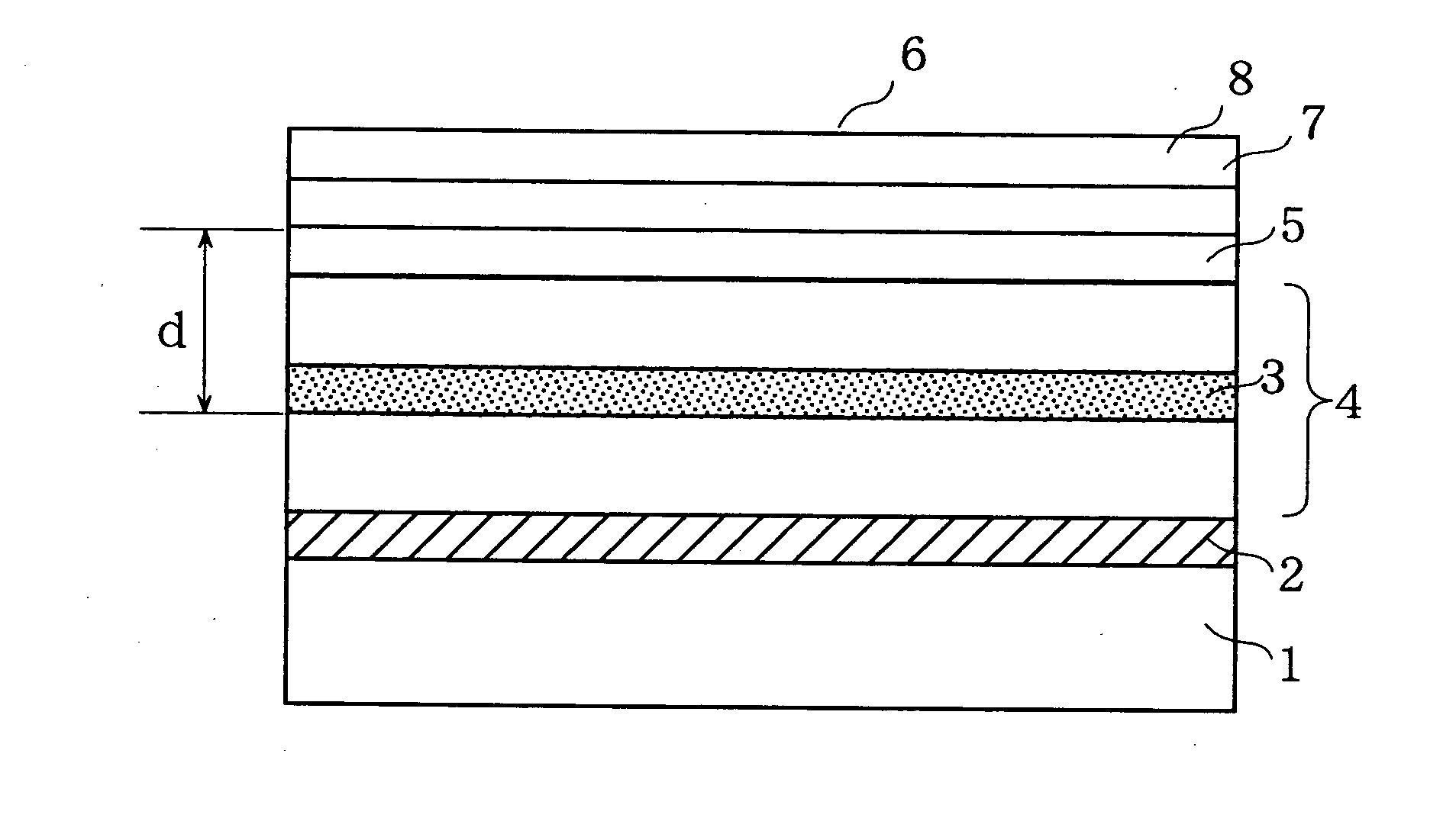
[0101] FIG. 1 is a cross-sectional view schematically showing a light-emitting element according to Embodiment 1, which corresponds to the foregoing first aspect. The light-emitting element is constructed such that on a substrate 1a reflective electrode 2 (a light-reflective first electrode layer), a light-emitting layer 4 having a light-emitting region 3 (specifically, the light-emitting layer comprises an electron-injecting layer, an electron transport luminescent material layer, a hole transport material layer, a buffer layer, and the like), a transparent electrode 5 (a transparent second electrode layer), an aerogel layer 7 with a refractive index of approximately 1, and a passivation layer 8 are stacked on top of each other in this order. A surface of the passivation layer 8 serves as a light-extracting surface 6.

[0102] For the substrate 1, any type of substrate can be used as long as it can support the light-emitting element. It is possible to use a resin su...

embodiment 2

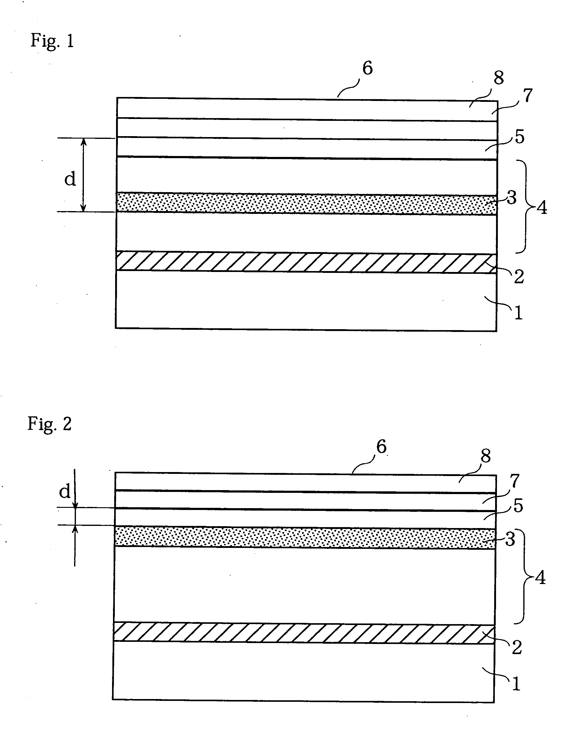
[0112] FIG. 2 is a cross-sectional view schematically showing a light-emitting element according to Embodiment 2, which corresponds to the foregoing first aspect. In the light-emitting element, a light-emitting region 3 exists in contact with a transparent electrode 5. In an element having such a construction, when the film thickness of the transparent electrode 5 is 50% or less of the peak wavelength of light emitted from the light-emitting region, most of the light at the critical angle or greater is not reflected due to the same principle as above, and thus the external extraction efficiency is increased.

[0113] Embodiments 1 and 2 described the case where a reflective electrode was used; however, even when an insulating and reflective layer, which is made, for example, of a mixture of a highly light reflective substance such as TiO.sub.2 or BaTiO.sub.3 and a highly dielectric substance such as cyanoethyl cellulose, is provided between the substrate and the first electrode or betw...

embodiment 3

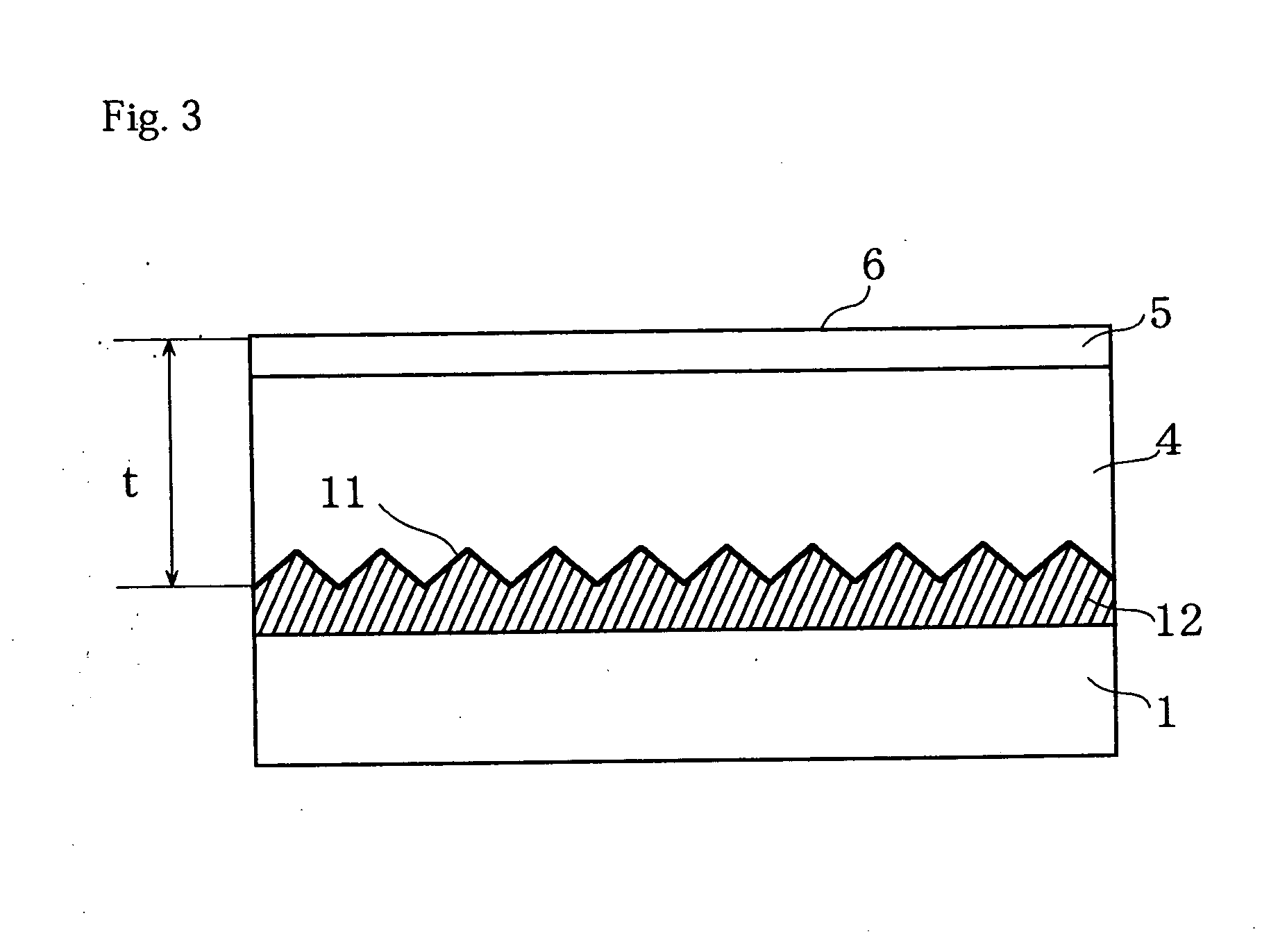
[0114] FIG. 3 is a cross-sectional view schematically showing a light-emitting element according to Embodiment 3, which corresponds to the foregoing second aspect. The light-emitting element is constructed such that on a substrate 1 a reflective electrode 12 having a light-scattering surface (irregular surface) 11, serving as a light-scattering portion, a light-emitting layer 4 having a light-emitting region 3, and a transparent electrode 5 are stacked on top of each other in this order. The surface of the transparent electrode 5 serves as a light-extracting surface 6.

[0115] In the present embodiment, a substrate provided with light-emitting elements, comprising a substrate and a plurality of the above-described light-emitting elements disposed on the substrate, was constructed such that the relationship between the distance between a reflective layer (the reflective electrode or an insulating and reflective layer) composing the light-emitting element, and the light-extracting surfa...


PUM


Abstract

A light-emitting element is provided having a layered structure composed of at least a light-emitting layer having a light-emitting region and a reflective layer for reflecting light emitted from the light-emitting region. Light emitted from the light-emitting region is extracted from a light-extracting surface distanced from the light-emitting region. A light-scattering portion is present in a part of the reflective layer.

Description

TECHNICAL FIELD[0001] The present invention relates to a self-luminous light-emitting element, a substrate provided with the light-emitting elements, and a display device and a lighting device that utilize the light-emitting element(s).BACKGROUND ART[0002] Light-emitting elements that emit light by applying an electric field thereto, such as electroluminescent (EL) elements and light-emitting diodes, are self-luminous, and thus have high visibility and can be made thin. For these reasons, such elements are attracting attention as lighting devices such as backlights and as display devices such as flat panel displays. Above all, organic EL elements that use organic compounds as emitters can be driven at low voltages, can be easily made large in area, and can easily obtain the desired emission color by selecting appropriate dyes, and thus are being actively developed as next-generation displays.[0003] For an EL element using an organic emitter, blue light emission is obtained by, for e...

Claims


Application Information

Patent Timeline
IPC IPC(8): H01L33/00H01L51/52
CPCH01L51/5262H01L2251/5315H01L51/5271H01L51/5268H10K2102/3026H10K59/877H10K59/878H10K50/856H10K50/85H10K50/854
Inventor SUGIURA, HISANORISATO, TETSUYAMATSUO, MIKIKOHATTA, SHIN-ICHIRO
Owner JOLED INC
Why Eureka
Try Eureka