Eureka AIR delivers breakthrough ideas for toughest innovation challenges, trusted by R&D personnel around the world.

Transmitter for automatically detecting power-down of transmitter and system including the same

A technology for transmitters and receivers, applied in the field of transmitters for automatic detection of receiver power failures and systems including the transmitters, capable of solving problems such as unreliable identification of power failures of receiving devices

Inactive Publication Date: 2011-08-10
SAMSUNG ELECTRONICS CO LTD
View PDF6 Cites 8 Cited by
  • Summary
  • Abstract
  • Description
  • Claims
  • Application Information

AI Technical Summary

Problems solved by technology

However, this only identifies whether the receiving device is connected or not connected, but does not reliably identify whether the receiving device has been powered down

Method used


Image

  • Transmitter for automatically detecting power-down of transmitter and system including the same
  • Transmitter for automatically detecting power-down of transmitter and system including the same
  • Transmitter for automatically detecting power-down of transmitter and system including the same

Examples


Embodiment Construction

[0036] The entire contents of Korean Patent Application No. 10-2010-0012481 filed with the Korean Intellectual Property Office on February 10, 2010, and the subject matter of which is: "Method for Automatically Detecting Power Loss of Receiver" is incorporated herein by reference in its entirety transmitters and systems including such transmitters."

[0037] Exemplary embodiments will be described more fully hereinafter with reference to the accompanying drawings; however, they may be embodied in different forms and should not be construed as limiting to the embodiments set forth in this specification. Rather, these embodiments are provided so that this disclosure will be thorough and complete, and will fully convey the scope of the invention to those skilled in the art. In the drawings, the size and relative sizes of layers and regions may be exaggerated for clarity. Like reference numerals refer to like elements throughout the specification.

[0038] In addition, it will a...


PUM


Abstract

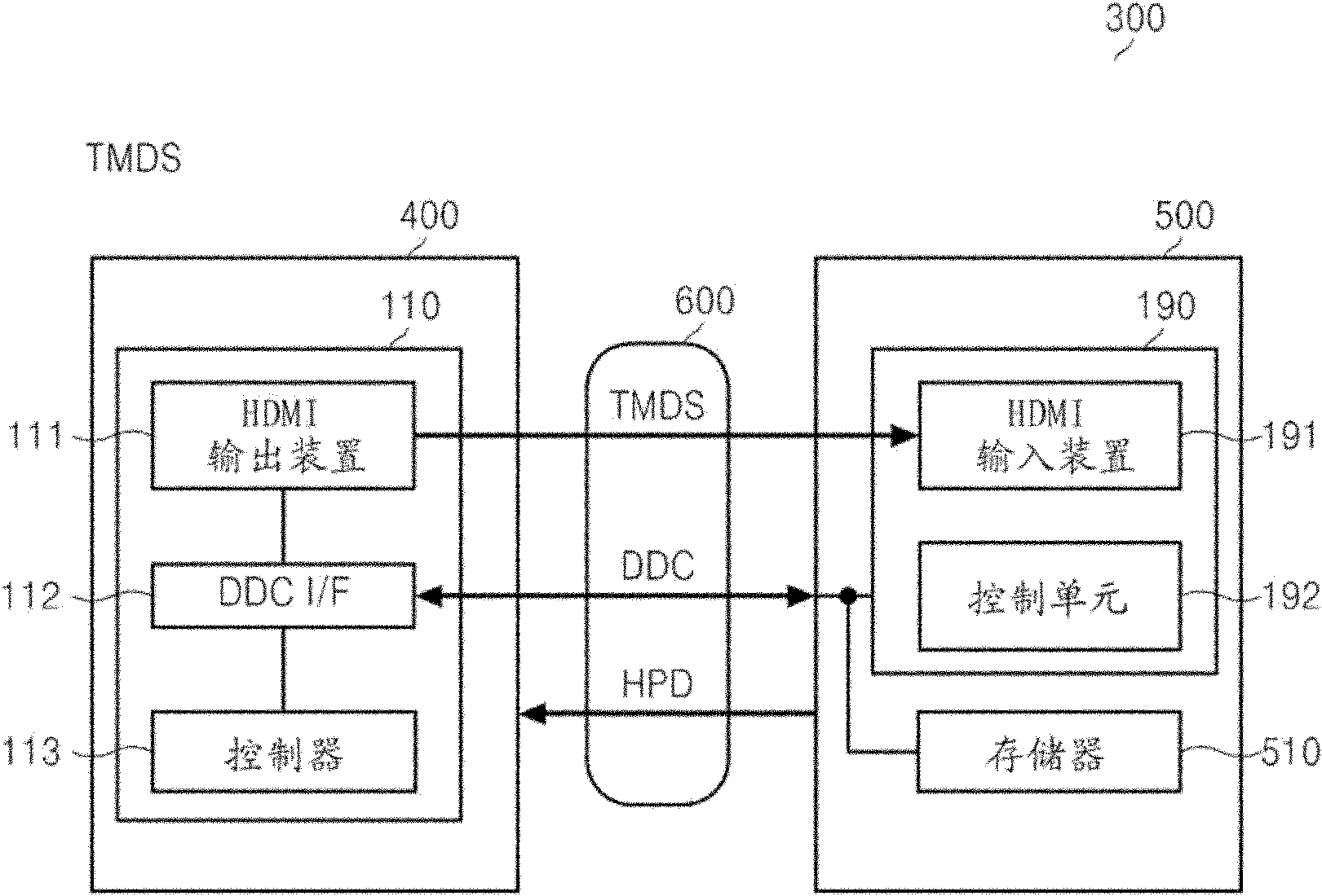
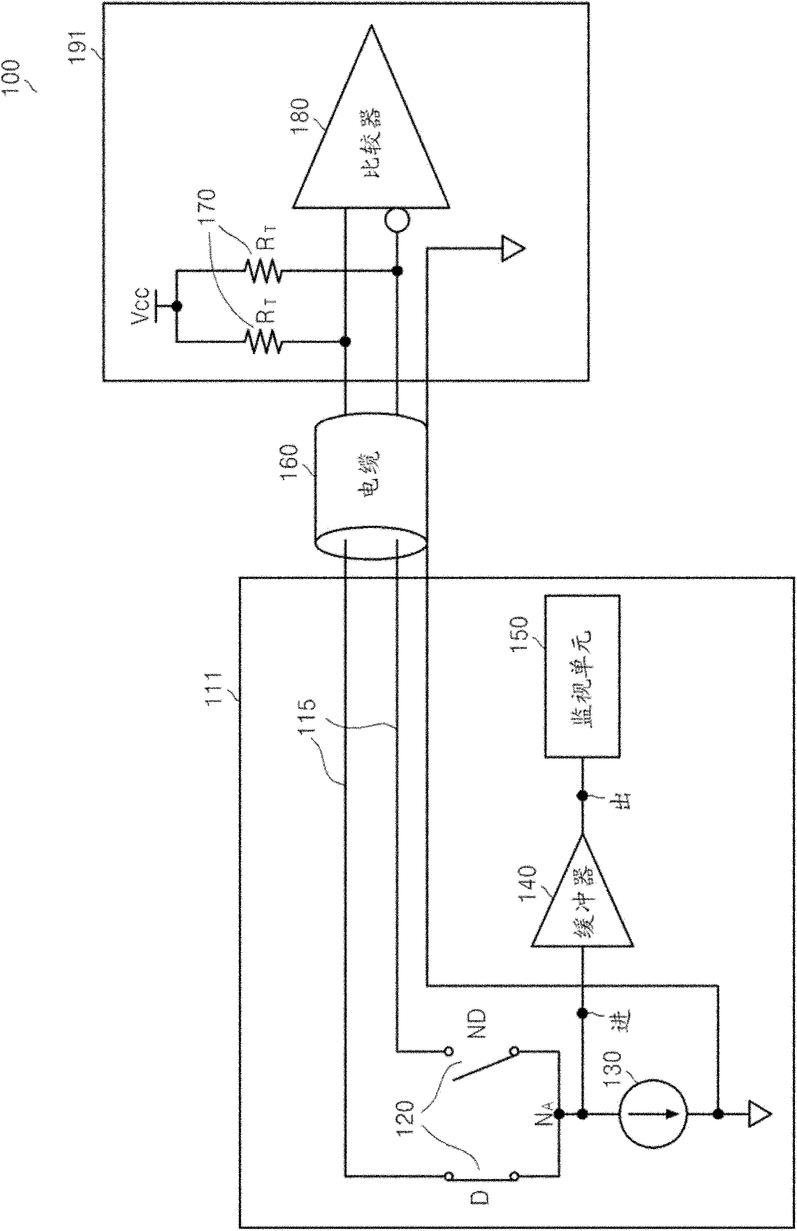
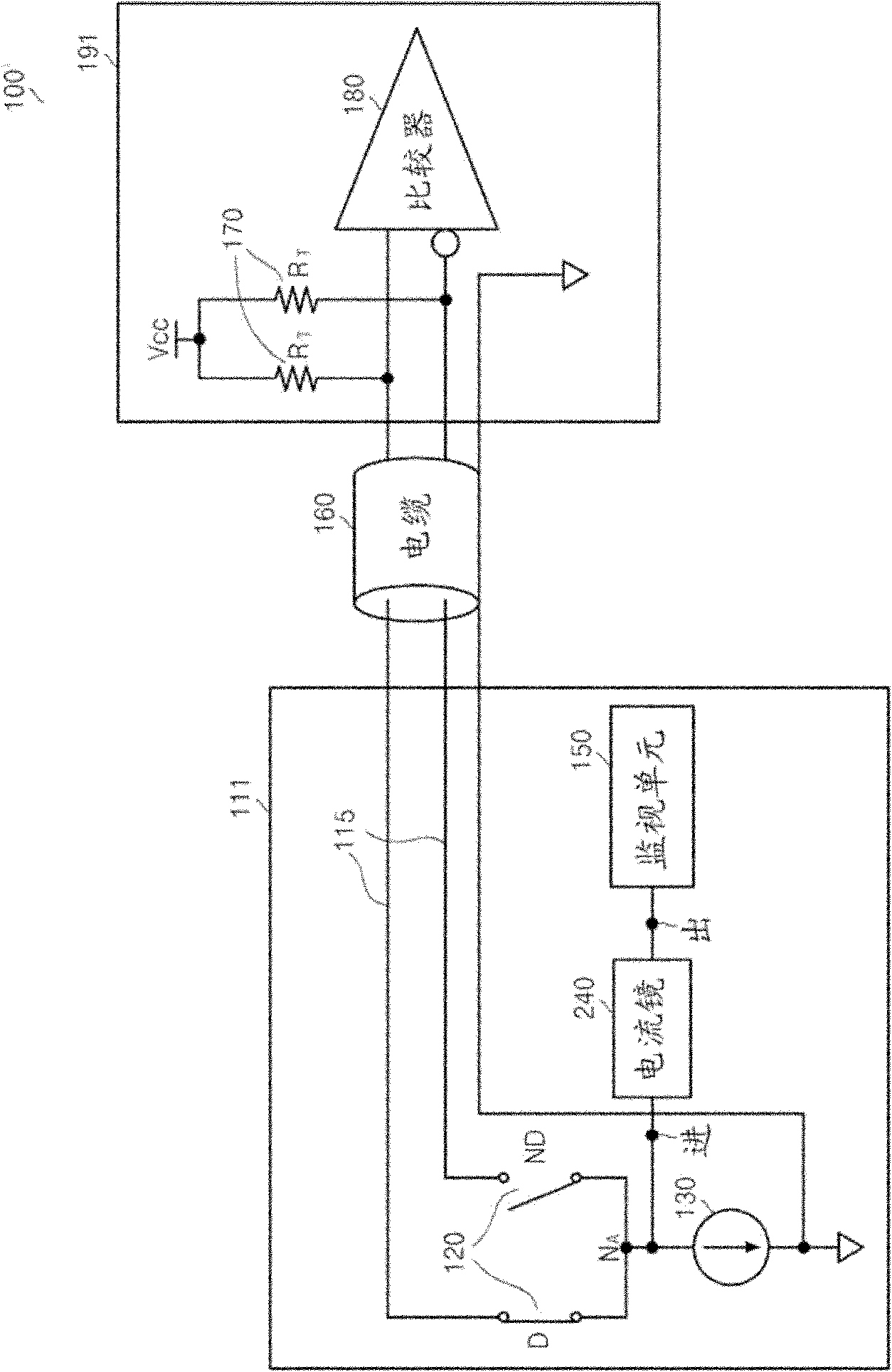
A transmitter of a transition minimized differential signaling (TMDS) system includes a current source, a pair of switches configured to be connected to the current source and switch a current of the current source, and a monitoring unit configured to monitor a potential of a connection node between the current source and the pair of switches. The pair of switches is connected to a receiver of the TMDS system through a first line and a second line, respectively. The monitoring unit monitors the potential of the connection node based on a power supply voltage applied to the receiver and current switching of the pair of switches.

Description

technical field [0001] Embodiments relate to a transmitter using a digital interface such as High-Definition Multimedia Interface (HDMI) or Digital Visual Interface (DVI) and a system including the same, and more particularly, to automatically detecting A powered-down transmitter of a receiver and a system including the transmitter. Background technique [0002] Recently, audiovisual (AV) systems including a source device transmitting AV data, a sink device receiving data, and a repeater device are being developed. Examples of source devices include Digital Video Disk (DVD) players, Blu-ray Disc (BD) players, High Definition (HD) DVD players, Compact Disk (CD) players. Examples of receiving devices include liquid crystal display (LCD) devices, plasma display panel (PDP) devices, and projectors. The repeater device may be an AV amplifier or AV receiver. [0003] These devices are connected to each other through an HDMI cable, and transmit and / or receive AV data through a d...

Claims


Application Information

Patent Timeline
Patent Type & Authority Applications(China)
IPC IPC(8): H04N5/765
CPCG09G2370/047H04N5/765H04N21/43635H04N21/44231G09G2330/021G09G2370/12G09G5/006G09G2330/12H04N21/4436H04L25/0272
Inventor 金好影
Owner SAMSUNG ELECTRONICS CO LTD
Why Eureka
Eureka Blog
Learn More