Electromagnetic shield panel, window member, structure, electromagnetic shield room and electromagnetic shield box

A technology of electromagnetic shielding and shielding components, applied in the fields of magnetic/electric field shielding, building components, electrical components, etc., can solve the problem that electromagnetic shielding panels cannot achieve shielding performance, etc., and achieve high electromagnetic shielding effect and improve rigidity.

Inactive Publication Date: 2011-08-10
TOKIN CORP +1
View PDF6 Cites 8 Cited by
  • Summary
  • Abstract
  • Description
  • Claims
  • Application Information

AI Technical Summary

Problems solved by technology

However, the electromagnetic shielding panel of Patent Document 1 cannot achieve such shielding performance

Method used


Image

  • Electromagnetic shield panel, window member, structure, electromagnetic shield room and electromagnetic shield box
  • Electromagnetic shield panel, window member, structure, electromagnetic shield room and electromagnetic shield box
  • Electromagnetic shield panel, window member, structure, electromagnetic shield room and electromagnetic shield box

Examples


no. 1 Embodiment approach

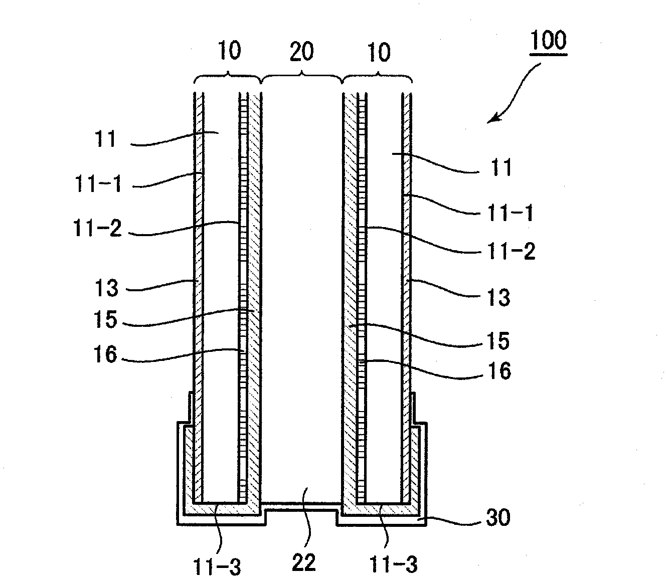
[0091] Such as figure 1 As shown, the electromagnetic shielding panel 100 according to the first embodiment of the present invention includes: a pair of shielding plates 10 ; a clamped body 20 clamped between the shielding plates 10 ; and a conductive member 30 for edge connection.

[0092] Each shielding plate 10 includes: an insulating plate 11, which has a first main surface 11-1, a second main surface 11-2 and four edges 11-3, and has high visible light transmittance; a high-frequency electromagnetic shielding member 13, The relatively high frequency domain has an electromagnetic shielding function; the low frequency electromagnetic shielding member 15 has an electromagnetic shielding function in a relatively low frequency domain.

[0093] The insulating plate 11 of this embodiment is comprised from a glass plate. However, the present invention is not limited thereto, and the insulating plate 11 may be a plate made of a resin having high visible light transmittance, such ...

no. 2 Embodiment approach

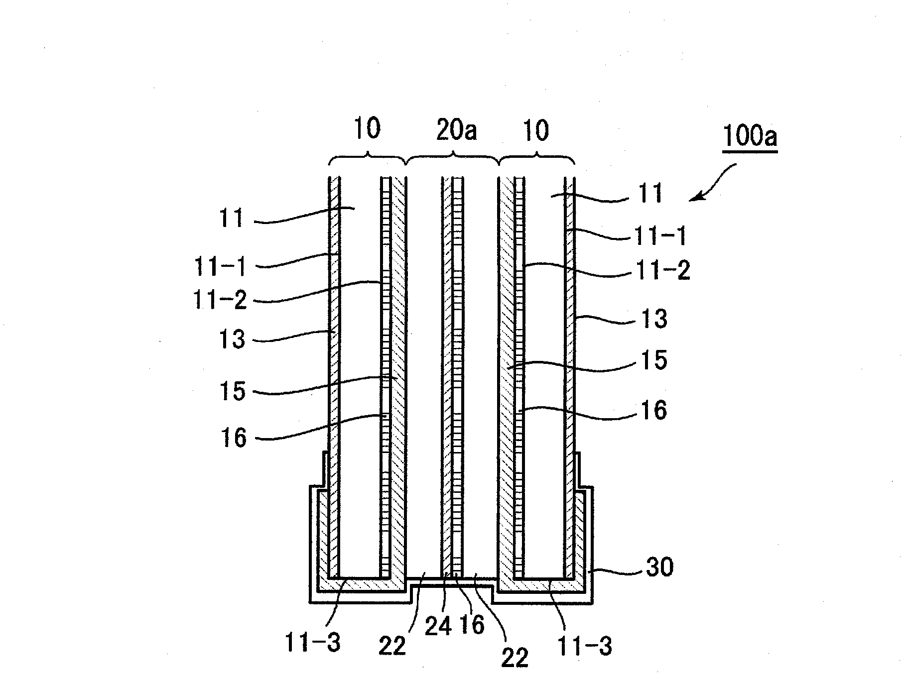
[0102] refer to image 3 , The electromagnetic shielding panel 100a of the second embodiment of the present invention is the same as the electromagnetic shielding panel 100 of the above-mentioned first embodiment except for the structure of the clamped body 20a. Therefore, only the differences are described below.

[0103] Such as image 3 As shown, the clamped body 20 a of this embodiment includes: a clamped insulator 22 composed of two glass plates; and a clamped high-frequency electromagnetic shielding member 24 . The clamped high-frequency electromagnetic shielding member 24 is fixed to the clamped insulator 22 on one side through the adhesive layer 16 , and is sandwiched by the two clamped insulators 22 . The clamped high-frequency electromagnetic shielding member 24 of this embodiment is composed of the same member as the high-frequency electromagnetic shielding member 13 , or may be composed of a member having the same function as the high-frequency electromagnetic sh...

no. 3 Embodiment approach

[0107] refer to Figure 4 The electromagnetic shielding panel 100b of the third embodiment of the present invention is the same as the electromagnetic shielding panel 100 of the above-mentioned first embodiment except for the configuration of the high frequency electromagnetic shielding member 17 except for the shielding plate 10b. Therefore, only the high-frequency electromagnetic shielding member 17 with differences will be described below.

[0108] The high-frequency electromagnetic shielding member 17 of the present embodiment is a conductive film composed of a conductive film 18 and an insulating film 19, and the conductive film 18 is arranged on the first main surface 11-1 of the insulating plate 11, and is arranged on it. Insulating film 19. By positioning the insulating film 19 outside in this way, the conductive thin film 18 can be protected from the outside. More specifically, the high-frequency electromagnetic shielding member 17 of this embodiment is a conductive...


PUM


Abstract

An electromagnetic shield panel is provided with at least a pair of shield plates and an edge connecting conductive member. Each shield plate is provided with: an insulating plate, which has a first main surface, a second main surface and four edges, and has visible light permeability; a high-frequency electromagnetic shield member, which has an electromagnetic shield function in a relatively high frequency region and is disposed to cover at least the first main surface; and a low-frequency electromagnetic shield member, which has an electromagnetic shield function in a relatively low frequency region and is disposed to cover at least the second main surface. In the electromagnetic shield panel, the insulating plate is wrapped with the high-frequency electromagnetic shield member and the low-frequency electromagnetic shield member by entirely covering all of the edges of the insulating plate with either the high-frequency electromagnetic shield member or the low-frequency electromagnetic shield member. The edge connecting conductive member physically and electrically connects all of the high-frequency electromagnetic shield members and the low-frequency electromagnetic shield members in the vicinity of all the edges of the pair of insulating plates.

Description

technical field [0001] The present invention relates to an electromagnetic shielding panel for shielding electromagnetic waves, in particular to an electromagnetic shielding panel with high electromagnetic shielding performance in a frequency band of about 30 MHz to 20 GHz. Furthermore, the present invention relates to a window member, a structure, an electromagnetic shielding room, and an electromagnetic shielding box constituted by an electromagnetic shielding panel. Background technique [0002] Patent Document 1 discloses an electromagnetic shielding panel that shields electromagnetic waves. The electromagnetic shielding panel of Patent Document 1 includes: two glass plates opposed to each other via a spacer; transparent conductive films formed on opposite surfaces of the glass plates; The transparent conductive film is electrically connected. [0003] (Prior Art Literature) [0004] (patent documents) [0005] Patent Document 1: Japanese Patent Application Publicati...

Claims


Application Information

Patent Timeline
Patent Type & Authority Applications(China)
IPC IPC(8): E06B3/66E04B1/92E06B5/00H05K9/00
CPCE06B5/18H05K9/0005E04B1/92E06B3/66E06B3/6621E06B3/66309E06B5/00H05K9/00H05K9/003H05K9/0088E04B2001/925
Inventor 加藤一美菅原健一
Owner TOKIN CORP
Why Eureka
Try Eureka