Stereoscopic video playback device and stereoscopic video display device

A technology of stereo vision and reproduction device, applied in stereo systems, image communication, electrical components, etc., can solve the problems of eye fatigue, OSD visual recognition decline, poor and other problems, and achieve the effect of improving visual recognition

Inactive Publication Date: 2011-08-10
PANASONIC CORP
View PDF9 Cites 11 Cited by
  • Summary
  • Abstract
  • Description
  • Claims
  • Application Information

AI Technical Summary

Problems solved by technology

However, when an OSD etc. is displayed in the visual direction of an object displayed before the constant depth, it appears to the viewer that the OSD etc. are trapped in the object
This not only reduces the visibility of the OSD, etc., but also may cause eye fatigue of the viewer, so it is not good.

Method used


Image

  • Stereoscopic video playback device and stereoscopic video display device
  • Stereoscopic video playback device and stereoscopic video display device
  • Stereoscopic video playback device and stereoscopic video display device

Examples


Embodiment approach 1

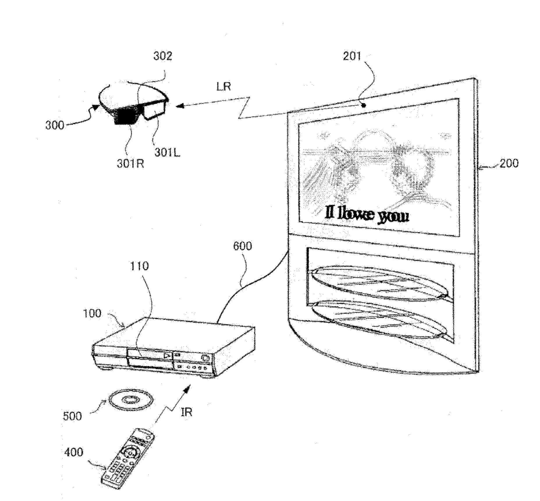
[0070] figure 1 It is a schematic diagram showing a stereoscopic video display system according to Embodiment 1 of the present invention. Such as figure 1 As shown, the system includes a playback device 100 , a display device 200 , liquid crystal shutter glasses 300 , a remote controller 400 and an optical disc 500 .

[0071] The optical disc 500 is, for example, a BD-ROM disc, and includes stereoscopic video content. In particular, both video streams for the left eye and audio streams for the right eye are multiplexed into one stream data.

[0072] The playback device 100 is mounted on, for example, an optical disc drive 110 conforming to the BD-ROM system. The playback device 100 uses the optical disc drive 110 to read stream data of stereoscopic video images from the optical disc 500 and decode them into video data / audio data. In particular, video data includes both left-eye and right-eye video frames. The playback device 100 is also connected to the display device 200...

Embodiment approach 2

[0330] In the playback device according to Embodiment 2 of the present invention, unlike the configuration of Embodiment 1, an operation mode for displaying content video / subtitles together with OSD as stereoscopic video can be selected. Other features, such as the data structure on the optical disc, the hardware configuration of the playback device, and the respective configurations of the control unit and the playback unit are the same as those of the first embodiment. Therefore, in the following description, features of Embodiment 2 that are different from those of Embodiment 1 will be described, and the description in Embodiment 1 will be referred to for features that are the same as those of Embodiment 1. FIG.

[0331] The playback device 100 causes the display device 200 to display a predetermined selection screen in accordance with a user's operation or an instruction from an application program. The display of the selection screen is performed by the OSD control module...

Embodiment approach 3

[0377] Unlike Embodiment 1, the playback device according to Embodiment 3 of the present invention enables the user to manually adjust the depth of the OSD. Other features, such as the data structure on the optical disc, the hardware configuration of the playback device, and the respective configurations of the control unit and the playback unit are the same as those of the first embodiment. Therefore, in the following description, features of Embodiment 3 that are different from those of Embodiment 1 are described, and the description in Embodiment 1 is referred to for features that are the same as those of Embodiment 1. FIG.

[0378] The OSD control module 1647 generates corresponding OSD graphics data GD2 according to the operation signal U0 or instructions from other modules 1644 and 1645 , and transmits it to the reproduction unit 170 . Thereafter, the OSD control module 1647 sends an OSD delete command RQ2 to the playback unit 170 in accordance with the elapse of a prede...


PUM


Abstract

A video plane generation unit decodes stream data into a pair of left-view and right-view video planes, and outputs the pair alternately in a 3D display mode and either of the pair repeatedly in a pseudo 2D display mode. An image plane generation unit generates a pair of left-view and right-view image planes having an OSD at different horizontal locations according to its depth to be perceived, and alternately output the pair of image planes. A pseudo 2D display control unit instructs the video plane generation unit to operate in the 3D display mode and the pseudo 2D display mode in periods where the image plane generation unit does not and does output the image planes, respectively. The adder unit combines a video plane and an image plane generated by the video plane generation unit and the image plane generation unit, respectively, onto a frame, and outputs the frame.

Description

technical field [0001] The invention relates to a display technology of a stereoscopic image, in particular to a technology of making an on-screen display (OSD) stereoscopically overlap the stereoscopic image. Background technique [0002] Display technology for stereoscopic images is expected to be a next-generation display technology, and its development has been rapidly advancing in recent years. This display technology basically utilizes the fact that "human beings perceive the three-dimensional shape and depth of objects based on binocular parallax" (for example, see Non-Patent Document 1). Specifically, two video frames of the same subject whose positions are slightly different in the horizontal direction are first photographed from one scene. One of these video frames is then projected to the viewer's left eye, while the other is projected to the right eye. At this time, the viewer perceives the three-dimensional shape and depth of the subject based on the slight di...

Claims


Application Information

Patent Timeline
Patent Type & Authority Applications(China)
IPC IPC(8): H04N13/04
CPCH04N13/0454H04N13/0456H04N13/007H04N13/004H04N13/0438H04N13/156H04N13/183H04N13/341H04N13/359H04N13/361
Inventor 中村智典杰尔马诺·莱希森林金丸智一
Owner PANASONIC CORP
Why Eureka
Try Eureka