
Pulse dynamic image information detecting device

A dynamic image and detection device technology, applied in the direction of catheters, etc., can solve the problems that restrict the research and application of the comprehensive pulse diagnosis information of TCM pulse diagnosis, the large difference, and the difficulty of fully and accurately reflecting the constituent elements of the pulse condition.

Inactive Publication Date: 2011-08-17
LANZHOU UNIVERSITY OF TECHNOLOGY
View PDF3 Cites 11 Cited by
  • Summary
  • Abstract
  • Description
  • Claims
  • Application Information

AI Technical Summary

Problems solved by technology

Due to the limitations of the type of sensors and the number of detection parts of these detection devices, it is difficult for the collected information to fully and accurately reflect the constituent elements of the pulse condition, which is quite different from the three-part nine-hour pulse-taking method of traditional Chinese medicine, which restricts the objectiveness of pulse diagnosis in traditional Chinese medicine. Research and application of comprehensive pulse diagnosis information

Method used


Image

  • Pulse dynamic image information detecting device
  • Pulse dynamic image information detecting device
  • Pulse dynamic image information detecting device

Examples


Embodiment Construction

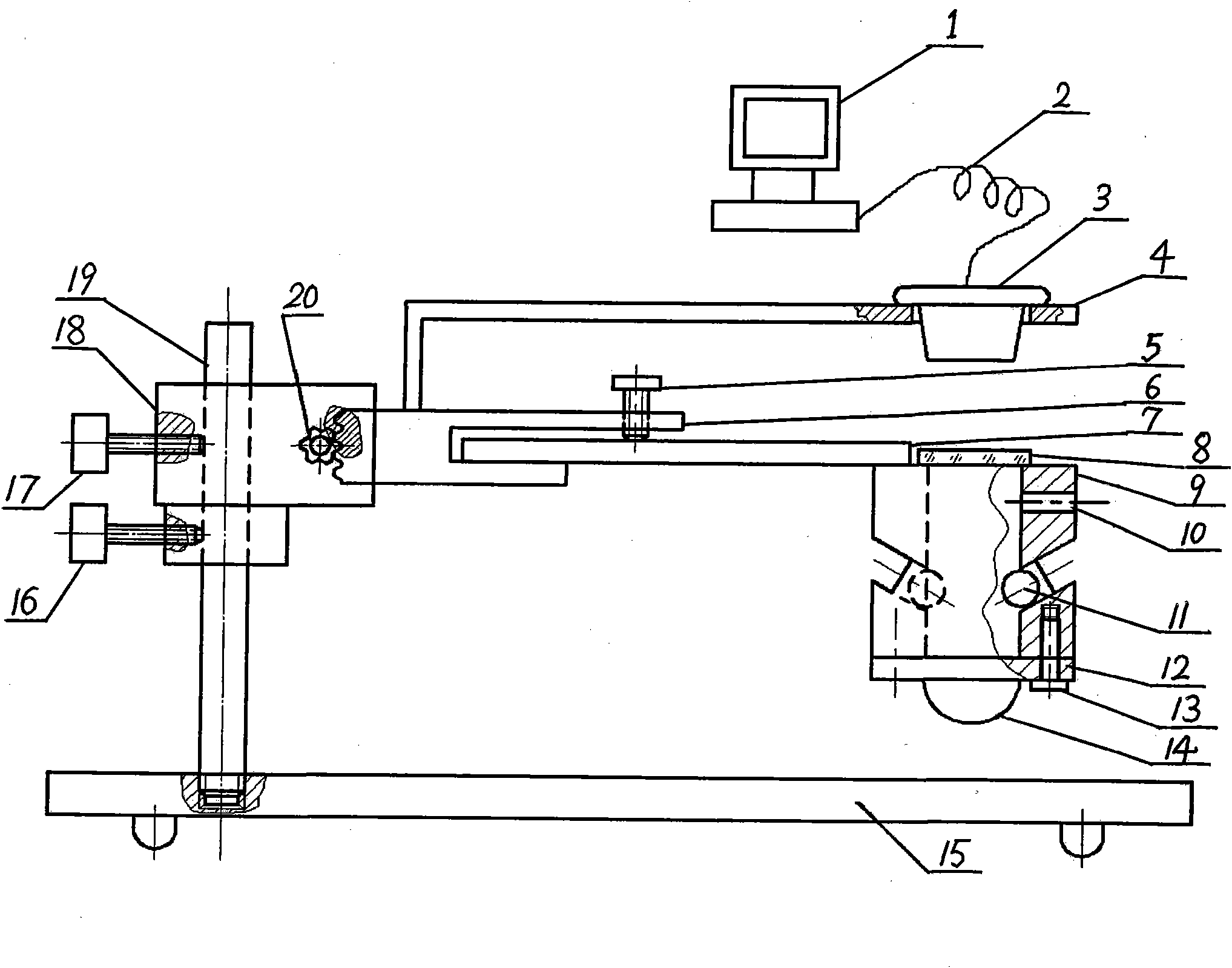
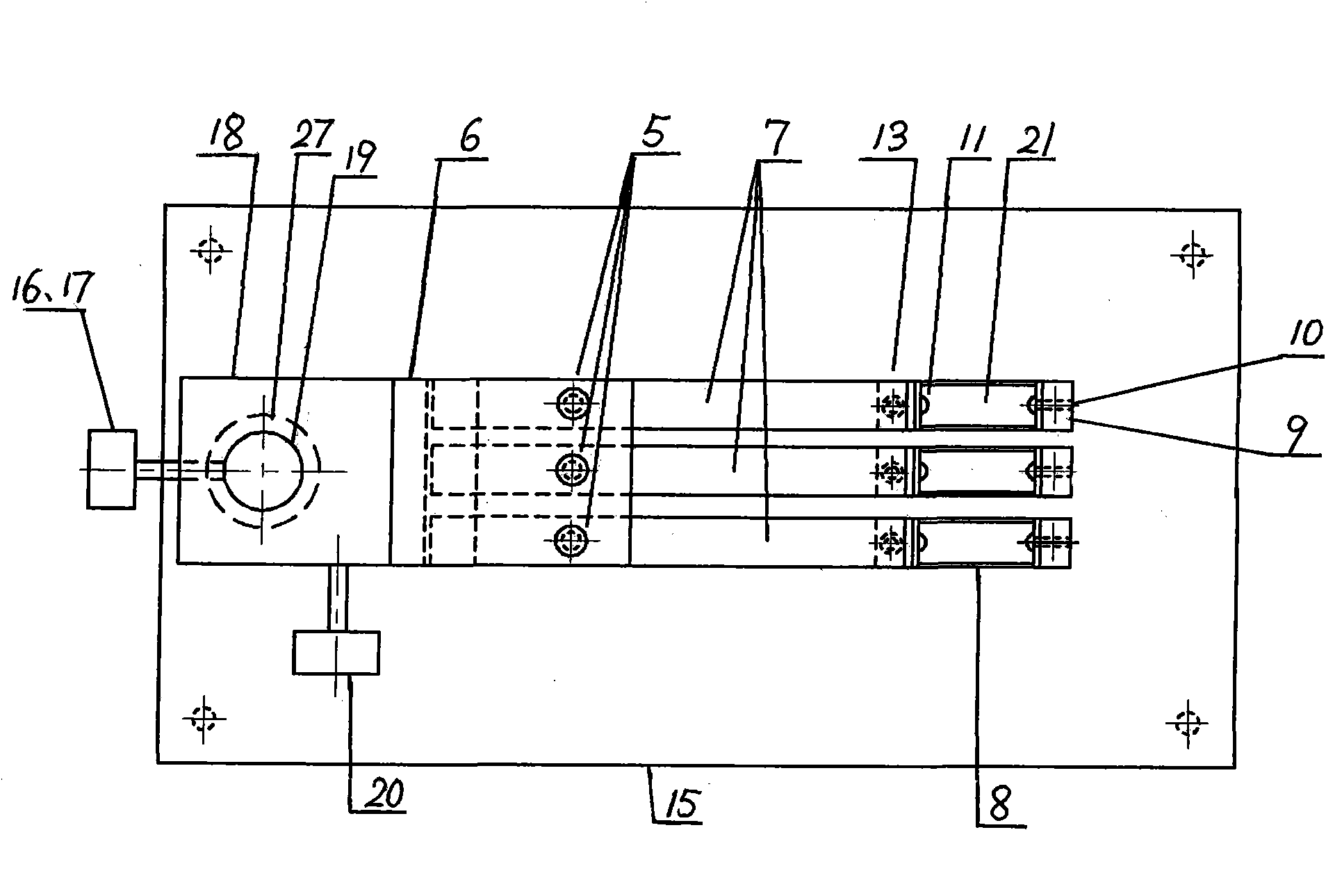
[0009] Such as figure 1 Shown, the present invention is the detection device of pulse dynamic image information, has a computer 1, and the data wire 2 of computer 1 connects CCD sensor 3, and base plate 15 is parallel with horizontal plane, and vertical shaft 19 is vertically installed on base plate 15, and slide block 18 Installed on the top of the vertical shaft 19, the Z-axis coarse adjustment knob 16 is installed on the ring 27 at the bottom of the slider 18, the Y-axis adjustment knob 17 is installed in the middle of the slider 18, and one end of the X-axis adjustment slider 6 passes through Z The axis fine-tuning knob 20 is installed on the slider 18 relative to the Z-axis coarse-adjusting knob 16; the other end of the X-axis adjusting slider 6 is provided with a groove parallel to the horizontal plane. The pressure adjustment knob 5 is installed in the above-mentioned groove, and a detection contact 9 is respectively installed at the other end; one end of the sensor bra...


PUM


Abstract

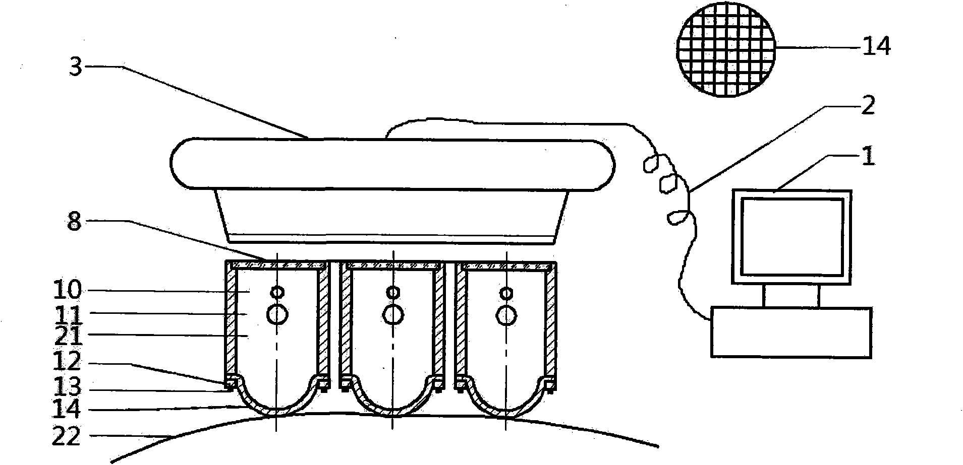
The invention provides a pulse dynamic image information detecting device, aiming at synchronously detecting the pulse information of the cun part, the guan part and the chi part during pulsing under the different pulse-taking pressures at the cun part, the guan part and the chi part. A slide block (18) is arranged at the upper part of a vertical axis (19), a Z-axis coarse-tuning knob (16) is arranged on a ring (27) at the lower part of the slide block (18), a Y-axis tuning knob (17) is arranged in the middle of the slide block (18), and one end of an X-axis tuning slide block (6) is arranged on the slide block (18) which is opposite to the Z-axis coarse-tuning knob (16) by a Z-axis fine-tuning knob (20); the other end of the X-axis tuning slide block (6) is in parallel with the horizontal plane and is provided with a groove, one end of an elastic bridge arm (7) is respectively arranged in the groove by a pulse-taking pressure tuning knob (5), and the other end of the elastic bridge arm (7) is respectably provided with a detecting contact head (9); one end of a sensor bracket (4) is arranged on the X-axis tuning slide block (6), and the other end of the sensor bracket (4) is provided with a CCD (charge coupled device) sensor (3); and the detecting contact head (9) is a cylindrical component with a seal cavity (21), a cylindrical wall of the detecting contact head (9) is provided with an air inlet (10), the upper end of the detecting contact head (9) is sealed by a photo-permeable glass piece (8), the lower end of the detecting contact head (9) is sealed by a silica gel film (14) with grid texture, a light source (11) is arranged in the middle of the cylindrical wall of the detecting contact head (9), the seal cavity (21) is connected with an air pressure cushion cavity (26) by an air pipe (24), the air pressure cushion cavity (26) is connected with a pressure gauge (23) by the air pipe.

Description

technical field [0001] The invention relates to a detecting device for pulse information of traditional Chinese medicine. Background technique [0002] At present, the detection devices for pulse information mainly include single-part, double-part, three-part and multi-point types. Single pulse information detection device is the most common. It only detects one of the three parts of inch, guan, and ruler. Most of the sensors used are pressure sensors, and the pulse information obtained is limited and one-dimensional. The double-part type can only detect the information of two of the three parts of inch, guan, and chi, and it is also one-dimensional information, and the amount of information is also limited. The three-part pulse detection system developed by Shanghai University of Traditional Chinese Medicine can extract the pulse signals of Cun, Guan and Chi, but it uses the strain-pressure sensing probe. In order to collect more comprehensive pulse information, Professor...

Claims


Application Information

Patent Timeline
IPC IPC(8): A61B5/02
Inventor 张爱华朱亮党宏智
Owner LANZHOU UNIVERSITY OF TECHNOLOGY
Learn More