Dynamic Synchronization Control Circuit of Satellite Sailboard Power Array Simulator

An array simulator and synchronous control technology, applied in the direction of single output arrangement, pulse shaping, etc., can solve the problems of small synchronization range, low frequency control accuracy, easy signal delay, etc., to achieve enhanced signal transmission capability, transient band The effect of improving the load capacity and improving the anti-jamming ability

Active Publication Date: 2016-03-30
CHINA ELECTRONIS TECH INSTR CO LTD
View PDF4 Cites 0 Cited by
  • Summary
  • Abstract
  • Description
  • Claims
  • Application Information

AI Technical Summary

Problems solved by technology

This kind of control process is relatively simple, the synchronization signal is relatively weak, and the synchronization range is small due to the influence of the synchronization signal amplitude; and the synchronization signal is easily interfered during transmission, and the signal is prone to delay
If the synchronization signal is amplified and the amplitude of the oscillator ramp voltage is changed, it is easy to cause the phase loss of the voltage control and slope compensation circuit, which greatly reduces the frequency control accuracy.
Therefore, in the synchronous control of the PWM signal, the above-mentioned control method has a low response speed, a small synchronous range, and a short transmission distance, and cannot realize fast synchronous adjustment of each output voltage.
Therefore, there is still a certain low-frequency beat intermodulation interference phenomenon between the main and auxiliary converters

Method used


Image

  • Dynamic Synchronization Control Circuit of Satellite Sailboard Power Array Simulator
  • Dynamic Synchronization Control Circuit of Satellite Sailboard Power Array Simulator
  • Dynamic Synchronization Control Circuit of Satellite Sailboard Power Array Simulator

Examples


Embodiment Construction

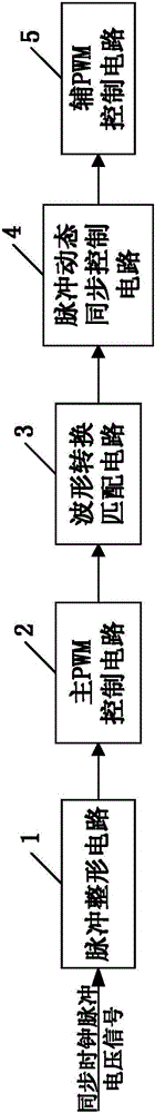
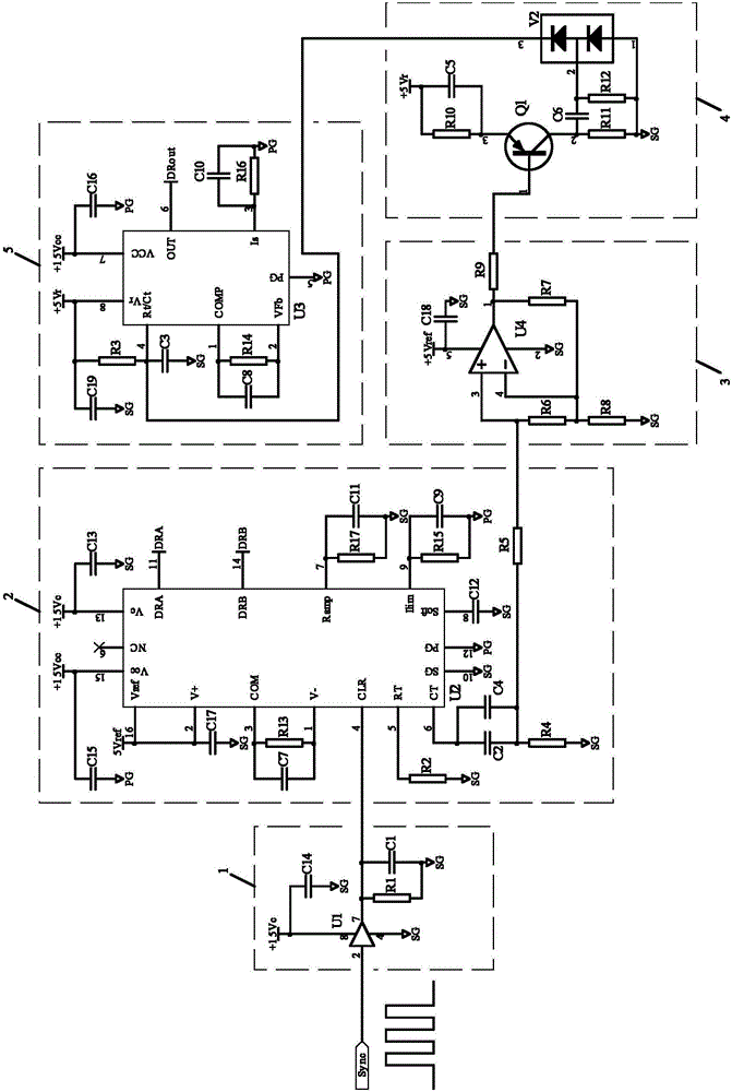
[0016] A dynamic synchronous control circuit of a satellite sailboard power supply array simulator, including a pulse shaping circuit 1 for receiving a synchronous clock pulse voltage signal, its output end is connected with the input end of a main PWM control circuit 2, and the main PWM control circuit 2 The output terminal is connected to the input terminal of the waveform conversion matching circuit 3, the output terminal of the waveform conversion matching circuit 3 is connected to the input terminal of the pulse dynamic synchronization control circuit 4, and the output terminal of the pulse dynamic synchronization control circuit 4 is connected to the input of the auxiliary PWM control circuit 5 The terminals are connected, the synchronous clock frequency of the pulse dynamic synchronization control circuit 4 is greater than the natural vibration frequency, and the pulse width output by the pulse dynamic synchronization control circuit 4 is 5% of the switching period, such ...


PUM


Abstract

The invention relates to a dynamic synchronous control circuit of a satellite sailboard power source array simulator. The dynamic synchronous control circuit comprises a pulse shaping circuit which is used for receiving synchronous clock pulse voltage signals, the output end of the pulse shaping circuit is connected with the input end of a main PWM (Pulse Wavelength Modulation) control circuit, the output end of the main PWM control circuit is connected with the input end of a wave shape conversion matching circuit, the output end of the wave shape conversion matching circuit is connected with the input end of a pulse dynamic synchronous control circuit, and the output end of the pulse dynamic synchronous control circuit is connected with the input end of an auxiliary PWM control circuit. The dynamic synchronous control circuit has the advantages that the anti-jamming capability of synchronous clock pulse voltage signals is improved by using the unified synchronous clock pulsed voltage signal through the pulse shaping circuit, and the transmission capability of signals is also greatly enhanced; and the synchronous range of circuits of the satellite sailboard power source array simulator is effectively widened, a series of switching power supply problems such as beat jamming and electromagnetic compatibility are obviously reduced, and the transient loading capacity of the system is also greatly improved.

Description

technical field [0001] The invention relates to the field of PWM dynamic synchronous control, in particular to a dynamic synchronous control circuit of a satellite sailboard power supply array simulator. Background technique [0002] The satellite sailing power array simulator system is based on the unit module power supply, and usually consists of multiple satellite sailing power array simulators. Since there are multiple switching converters in the system, each switching converter has its own work The switching frequency not only increases the difficulty of designing various key parameters of the switching converter, but also each switching converter has different electromagnetic interference frequencies, and the electromagnetic compatibility design of the system becomes very complicated. In addition, there is mutual intermodulation interference between multiple switching converters, which produces low-frequency beat noise, which makes the electromagnetic interference prob...

Claims


Application Information

Patent Timeline
Patent Type & Authority Patents(China)
IPC IPC(8): H03K5/01H03K5/13
Inventor 李斌王文廷王群
Owner CHINA ELECTRONIS TECH INSTR CO LTD
Why Eureka
Try Eureka