Scrap chute mechanism

A chute and waste technology, applied in the field of waste chute mechanism, can solve the problems of difficult discharge of waste, unsmooth discharge, increased mold closing height, etc., and achieve the effect of reducing design restrictions, improving reliability, and smooth discharging

Inactive Publication Date: 2011-08-17
CHERY AUTOMOBILE CO LTD
View PDF7 Cites 10 Cited by
  • Summary
  • Abstract
  • Description
  • Claims
  • Application Information

AI Technical Summary

Problems solved by technology

[0002] In order to ensure that the waste material can fall freely in the existing mold, the angle of the waste material chute is usually designed to be above 25° in the mold design, which requires the mold to have a larger lower mold height, which leads to an increase in the closed height of the mold
However, due to the influence of the production press or other aspects, the closing height of some molds cannot be designed very high, which leads to difficulties in discharging waste or unsmooth discharge of this part of the mold
However, automatic production has very strict requirements on the smoothness of waste discharge. Once the waste is not discharged smoothly and the material is piled up, it will cause abnormal stoppage.
According to relevant statistics, abnormal stoppages caused by poor waste discharge account for more than 60% of the total stoppages. Therefore, it can be said that waste discharge has become an urgent problem in mold design.

Method used


Image

  • Scrap chute mechanism
  • Scrap chute mechanism
  • Scrap chute mechanism

Examples


Embodiment 1

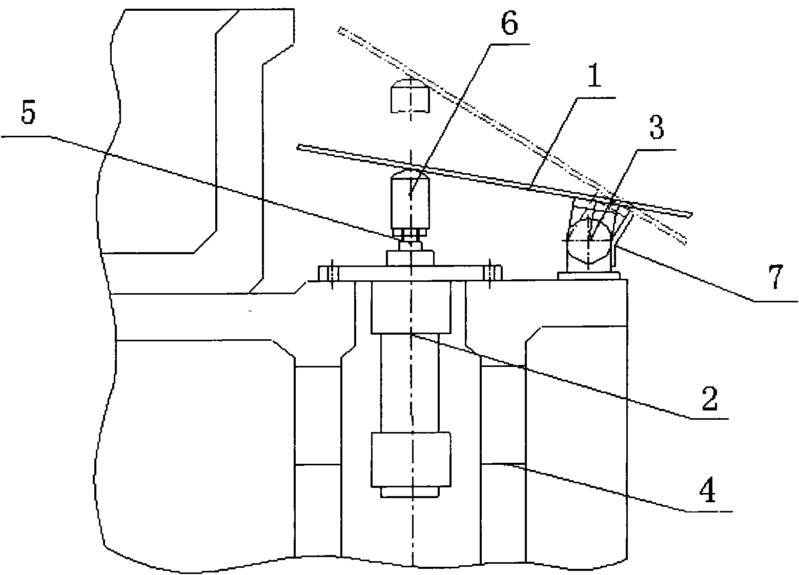
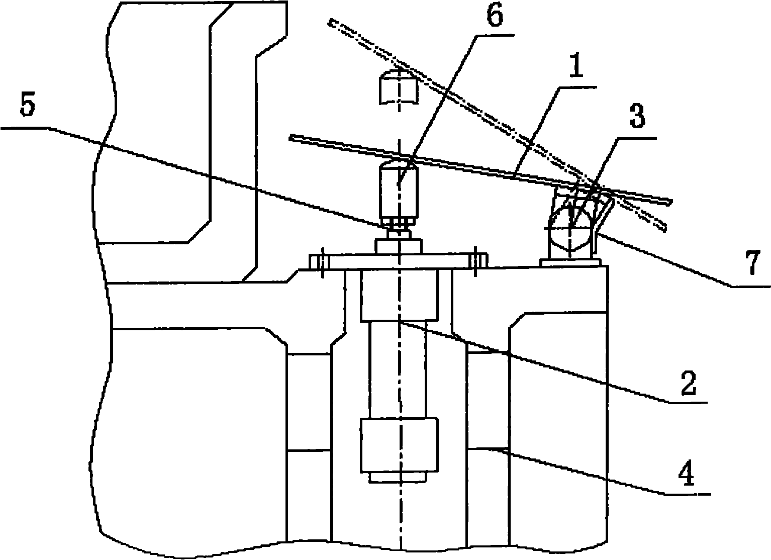
[0016] Such as figure 1 As shown, the waste chute mechanism of the present embodiment includes a waste chute 1 and a cylinder 2, the waste chute 1 is movably mounted on the lower die body 4 through a hinge 3, the cylinder 2 is vertically installed on the bottom of the waste chute 1, and the cylinder The end of the piston rod 3 is equipped with a top pin 6 with a spherical top surface, and the top pin 6 is offset against the bottom of the waste chute 1; the lower die body 4 is equipped with a limit plate 7 for limiting the rotation angle of the waste chute 1, so that The bottom of the positioning plate 7 is fixed on the lower mold body 4, and the upper part of the limiting plate 7 is bent toward the discharge direction.

[0017] When working, the piston rod 5 of the cylinder continuously reciprocates and vertically moves under the action of the gas. When the piston rod 5 moves upward, it can lift the waste chute 1, because the waste chute 1 is restricted by the hinge 3 below it...

Embodiment 2

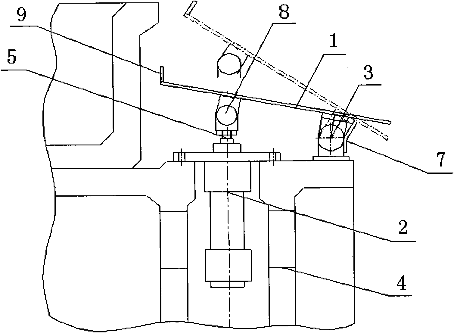
[0019] Such as figure 2 As shown, the waste chute mechanism of the present embodiment includes a waste chute 1 and a cylinder 2, the waste chute 1 is movably mounted on the lower die body 4 through a hinge 3, the cylinder 2 is vertically installed on the bottom of the waste chute 1, and the cylinder The end of the piston rod 3 is flexibly connected to the bottom of the waste chute 1 through a hinge 8; the lower mold body 4 is equipped with a limit plate 7 for limiting the rotation angle of the waste chute 1, and the bottom of the limit plate 7 is fixed on the lower mold body 4, the upper part of the limit plate 7 is bent toward the discharge direction; the end of the waste chute 1 away from the discharge direction is equipped with a vertical rib 9.

[0020] When working, the piston rod 5 of the cylinder continuously reciprocates and vertically moves under the action of the gas. When the piston rod 5 moves upward, it can lift the waste chute 1, because the waste chute 1 is res...


PUM


Abstract

The invention aims to provide a scrap chute mechanism which can smoothly discharge materials under a condition that the height of a lower mould is small so as to reduce limit on design of the mould. The scrap chute mechanism comprises a scrap chute and an air cylinder, wherein the scrap chute is arranged on a lower mould body through a hinge; the air cylinder is vertically arranged at the lower part of the scrap chute; the end of a piston rod of the air cylinder is movably connected with or pushes against the bottom of the scrap chute. When the mechanism works, the piston rod of the air cylinder reciprocates vertically and constantly under the action of air, and the piston rod can jack the scrap chute up when moving upwards; the scrap chute can only rotate around the hinge because the scrap chute is limited by the hinge under the scrap chute; the angle of the scrap chute is increased in the rotating process, and scrap can be smoothly discharged. The scrap chute mechanism has a simple structure and can discharge smoothly under a condition that the angle of the scrap chute is small, therefore the design limit of the mould is reduced, and the reliability of automatic production is improved.

Description

technical field [0001] The invention belongs to the technical field of automobile cold stamping dies, and in particular relates to a waste material chute mechanism. Background technique [0002] In order to ensure that the waste material can fall freely in the existing mold, the angle of the waste material chute is usually required to be designed above 25° during the mold design, which requires the mold to have a larger lower mold height, thereby resulting in an increase in the closed height of the mold. However, due to the influence of the production press or other aspects, the closing height of some molds cannot be designed to be very high, which leads to difficulties in discharging waste or unsmooth discharge of this part of the mold. However, automatic production has very strict requirements on the smoothness of waste discharge. Once the waste is not discharged smoothly and the material is stacked, it will cause abnormal stoppage. According to relevant statistics, abnor...

Claims


Application Information

Patent Timeline
Patent Type & Authority Applications(China)
IPC IPC(8): B21D45/02
Inventor 雷金宝吴立军
Owner CHERY AUTOMOBILE CO LTD
Why Eureka
Try Eureka