
Equipment for processing tooth surface of gear

A processing equipment and tooth surface technology, which is applied in the field of gear tooth surface processing equipment, can solve the problems that the diameter of the tooth surface of the gear cannot be guaranteed to be consistent, the stability of the large and small columns is different, etc. handy effect

Active Publication Date: 2011-08-17
绍兴骏马机械制造有限公司
View PDF6 Cites 4 Cited by
  • Summary
  • Abstract
  • Description
  • Claims
  • Application Information

AI Technical Summary

Problems solved by technology

The gear tooth surface processing equipment composed of the above structure, its large column and small column are installed on the machine base, and the upper ends are suspended in the air. When processing gears with low height, the rigidity of the large and small columns can basically ensure that the workpiece is processed up and down. The diameter of the end is consistent; but when processing a gear with a large height, in view of the rigidity of the large and small columns, when the milling tool is processing the workpiece, the difference in the upper and lower positions will produce different lateral forces between the large and small columns, resulting in large and small Due to the difference in the stability of the column, it is difficult to ensure the consistent diameter of the processed gear tooth surface, resulting in different taper of the processed tooth surface

Method used


Image

  • Equipment for processing tooth surface of gear
  • Equipment for processing tooth surface of gear

Examples


Embodiment Construction

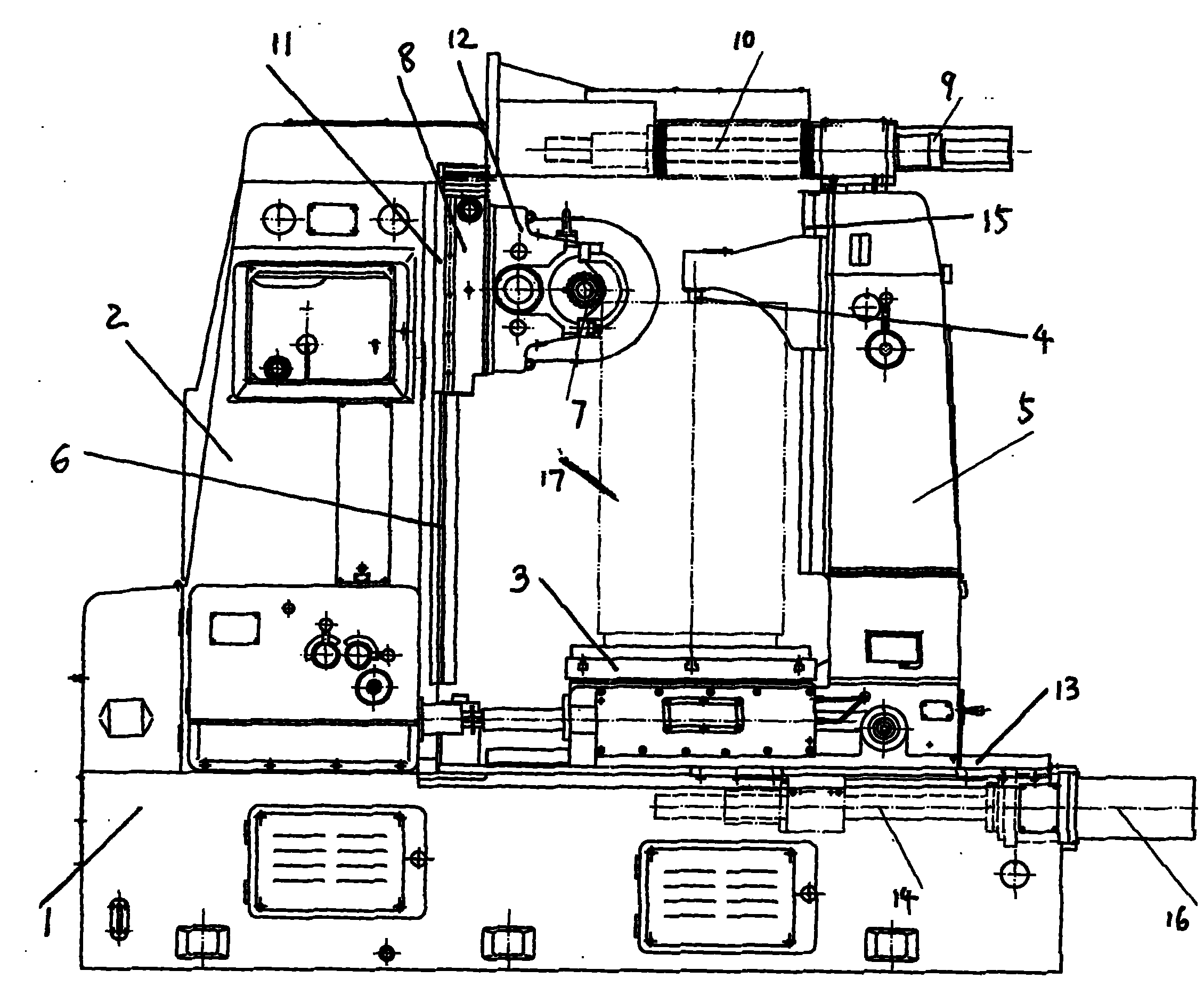
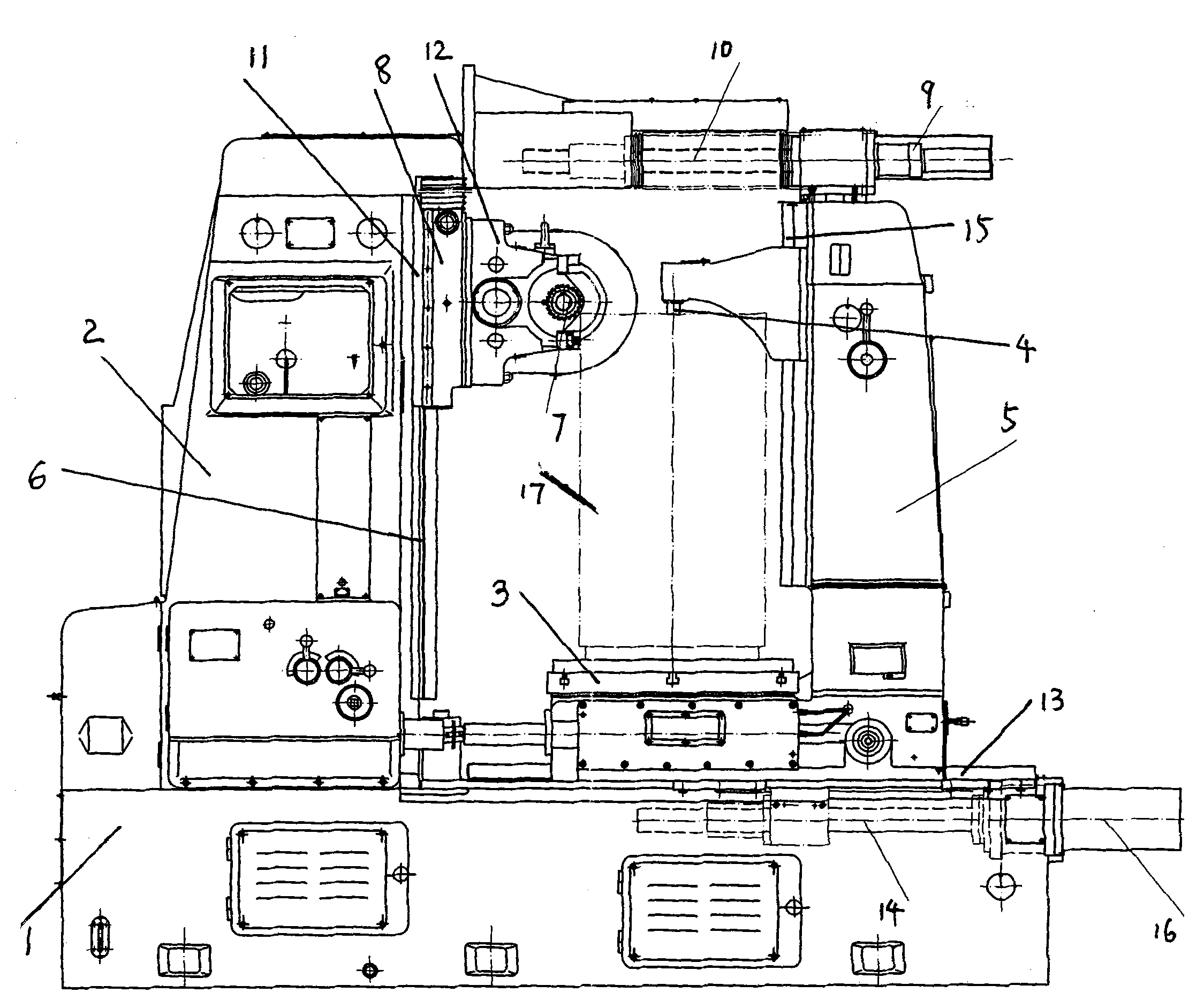
[0010] The present invention will be described in detail below in conjunction with accompanying drawing: figure 1 As shown, the present invention mainly includes: a machine base 1, a large column 2 on the machine base 1, a working turntable 3 for clamping a workpiece 17, a small column 5 with a top 4 connected to the working turntable 3, And be installed on the large column 2 and can move up and down along the large guide rail 6 on the large column, the slide plate frame 8 that can install the milling tool 7, horizontally placed between the described large column 2 upper end and the small column 5 upper end Adjust the screw mechanism of the position between the two; the screw mechanism shown in the figure is made up of an adjustable position screw rod 10 with a servo motor 9 .

[0011] figure 1 The large column 2 shown in the figure is fixedly placed on the machine base 1, and the slide frame 8 is composed of a slide plate 11 that can slide up and down on the large guide rail...


PUM


Abstract

The invention provides equipment for processing a tooth surface of a gear. The equipment mainly comprises a machine base, a large stand column arranged on the machine base, a working turntable for clamping a workpiece, a small stand column which is connected with the working turntable and provided with a tip, and a sliding plate frame which is arranged on the large stand column, capable of movingup and down along a guide rail of the large stand column and used for installing a milling cutter; a screw rod mechanism capable of adjusting a position between the large stand column and the small stand column is transversely arranged between the upper end of the large stand column and the upper end of the small stand column; the large stand column is fixed on the machine base; the sliding plateframe consists of a sliding plate capable of sliding up and down on the large guide rail, and a milling cutter frame fixed on the sliding plate; the working turntable is arranged on a transverse guide rail on the machine base in the north and capable of moving left and right; the lower part of the working turntable is connected with a lower screw rod with a servo motor; and the tip capable of moving up and down on a vertical small guide rail of the small stand column is arranged on the small stand column connected with the working turntable. The equipment for processing the tooth surface of the gear has the characteristics of meeting the requirement of the processing precision of the tooth surface of the gear by test and control adjustment, along with simple structure and convenience for use and installation.

Description

technical field [0001] The invention relates to a processing equipment specially for processing gear tooth surfaces, including gear hobbing machines, gear grinding machines and other equipment, belonging to mechanical processing equipment. Background technique [0002] In the prior art, equipment used for machining gear tooth surfaces mainly includes gear hobbing machines, gear grinding machines, and the like. These devices are mainly composed of a machine base, a large column, a small column, a working turntable specially used for clamping workpieces, and a slide frame installed on the large column for clamping grinding and milling tools. The processed workpiece is placed on the working turntable, and the top connected with the small column is crimped on the working turntable and fixed. When working, the skateboard frame moves up and down along the vertical guide rail on the large column, so that the skateboard frame is fixed. The grinding and milling tool realizes the upp...

Claims


Application Information

Patent Timeline
Patent Type & Authority Applications(China)
IPC IPC(8): B23F23/00
Inventor 陈建文
Owner 绍兴骏马机械制造有限公司
Learn More