Ultra-narrow gap welding device and method for U-shaped flux strip constraining arc

A welding device and welding method technology, applied in arc welding equipment, electrode support devices, welding equipment, etc., can solve problems such as inability to effectively restrain the welding arc, inconvenient welding torch welding, and complex overall structure of the welding torch

Inactive Publication Date: 2011-08-17
LANZHOU UNIVERSITY OF TECHNOLOGY
View PDF8 Cites 9 Cited by
  • Summary
  • Abstract
  • Description
  • Claims
  • Application Information

AI Technical Summary

Problems solved by technology

The test found that there is a problem with the confined arc welding method of pasting the flux tape. When cleaning the welding slag, it is easy to cause the damage on the remaining flux tape to fall off, which will affect the welding of the next weld.
The disadvantage of this welding torch is that the flux strip is fed continuously through the belt feeder, and the feeding amount and position of the flux strip are prone to change during the welding process, which cannot effectively restrain the welding arc and affect the stability of the welding arc; The clamping force of the welding wire is adjusted by the elastic deformation force of the spring sheet itself, so that the spring sheet is prone to plastic deformation and the elastic deformation force is reduced; there is a guide rod on the insulating plate of the plate-type contact tip, although it can prevent the contact tip from It is in contact with the side wall of the groove, but the interference of the side wall to the welding arc cannot be completely avoided. The horizontal section of the type contact tip is still easy to arc with the side wall after entering the groove, causing the arc to rise; the overall structure of the welding torch is complicated, and the accessories need to be disassembled Too many bolts are used for connection, which is not convenient for the welding torch to extend into the groove for welding of greater thickness

Method used


Image

  • Ultra-narrow gap welding device and method for U-shaped flux strip constraining arc
  • Ultra-narrow gap welding device and method for U-shaped flux strip constraining arc
  • Ultra-narrow gap welding device and method for U-shaped flux strip constraining arc

Examples


Embodiment Construction

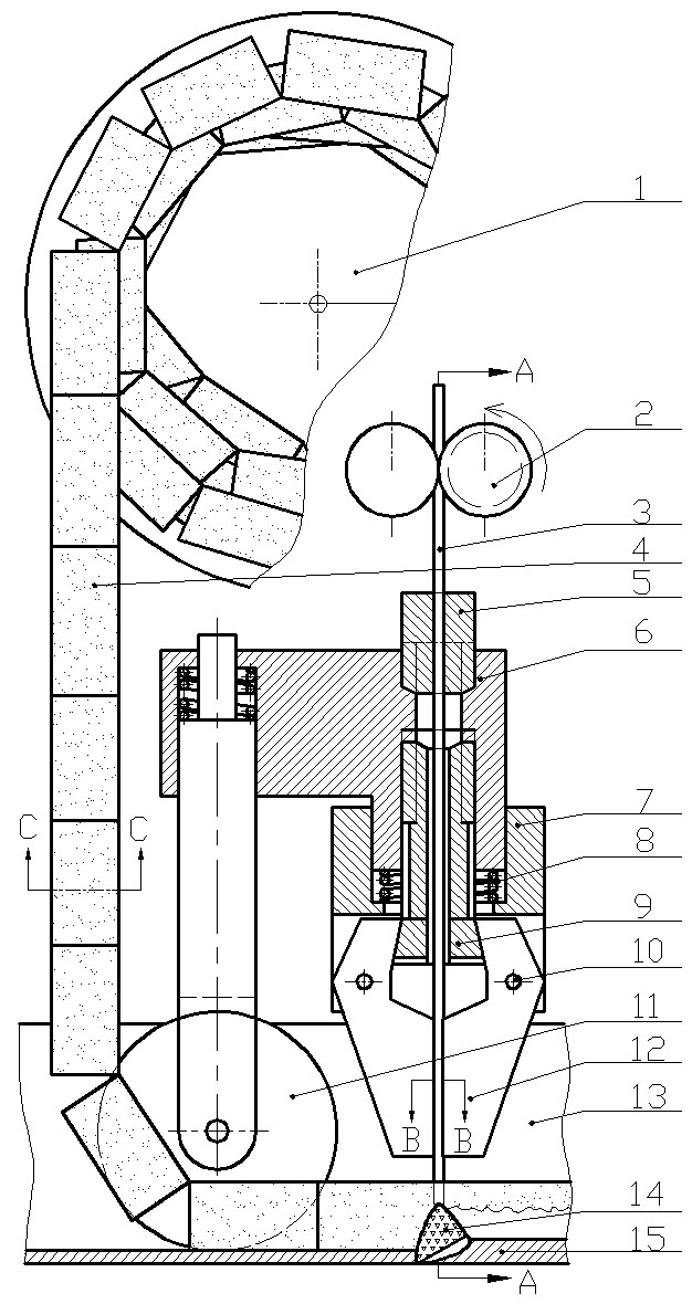
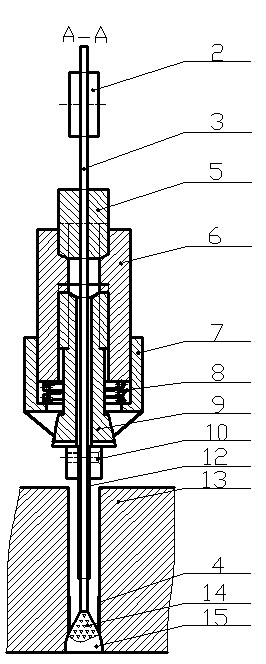
[0009] Such as figure 1 , figure 2 As shown, the U-shaped flux strip confined arc ultra-narrow gap welding device is composed of a flux strip laying mechanism and a welding torch. The U-shaped flux strip is composed of two parts: flux and steel wire mesh. On the top, the U-shaped flux belt 4 is pressed into the groove gap in front of the arc 14 through the pressure belt wheel 11 and is close to the side wall of the groove. On the base 7, the conductive sheet 12 can rotate around the screw 10, the compression spring 8 is set on the adjustment stem 9, and the adjustment stem 9 together with the compression spring 8 is installed on the welding torch support 6; the pressure belt wheel 11 is installed on the connecting rod, The upper end of connecting rod is arranged on the welding torch support 6 together with compression spring, and the size of the pressure band wheel 11 thickness is equal to the size of the exposed wire mesh width in the middle of the U-shaped solder band.

...


PUM

PropertyMeasurementUnit
thicknessaaaaaaaaaa
widthaaaaaaaaaa
thicknessaaaaaaaaaa

Abstract

The invention discloses an ultra-narrow gap welding device and method for a U-shaped flux strip constraining arc. A U-shaped flux strip (4) is wound on a flux strip winding disc (1), pressed into a groove gap in front of an arc (14) via a pinch roller (11) and tightly adhered to the sidewall of a groove, a welding wire (3) enters a current contact nozzle via a godet wheel, a conductive sheet (12) is installed on a current contact nozzle base (7) through a screw (10) and can rotate around the screw (10), a compression spring (8) is sleeved on an adjusting core column (9), and the adjusting core column (9) and the compression spring (8) are installed on a welding gun support base (6); the pinch roller (11) is installed on a connecting rod, the upper end of the connecting rod and the compression spring are installed on the welding gun support base (6); and I-shaped groove is adopted during welding, the U-shaped flux strip is pressed into the groove gap in front of the arc, the welding wire enters into the U-shaped flux strip to generate the flux strip constraining arc (14), the arc is limited to be combusted within a certain range at the bottom of the gap, and the molten flux strip forms a slag-covered molten pool.

Description

technical field [0001] The present invention relates to welding technology. Background technique [0002] The welding method with flux belt restraint arc can prevent the arc from climbing along the side wall, effectively control the heating area of ​​the arc, and ensure the effective fusion of the two sides of the groove and its root. There are two developed ultra-narrow gap welding methods for flux strip confined arc, one is to paste the flux strip on the side wall of the straight groove first, and then use the melting electrode arc to perform single-pass multi-layer welding; the other is top-down The flux strip with specific composition along the groove is continuously fed into both sides of the arc, and the matching welding torch is used to realize ultra-narrow gap welding. The test found that the problem with the confined arc welding method of pasting the flux tape is that it is easy to cause damage on the remaining flux tape to fall off when cleaning the welding slag, ...

Claims


Application Information

Patent Timeline
Patent Type & Authority Applications(China)
IPC IPC(8): B23K9/16B23K9/28
Inventor 朱亮王洪涛李宗志冯志鹏
Owner LANZHOU UNIVERSITY OF TECHNOLOGY
Why Eureka
Try Eureka