Eureka AIR delivers breakthrough ideas for toughest innovation challenges, trusted by R&D personnel around the world.

Device special for airplane launch

A technology of aircraft and control devices, which is applied in the direction of launching/dragging transmission devices, etc., can solve the problems of large fuel consumption, long aircraft, and only one aircraft can take off, and achieve the effects of improved survivability, stable thrust, and simple structure

Inactive Publication Date: 2013-10-16
XUZHOU UNIV OF TECH
View PDF4 Cites 0 Cited by
  • Summary
  • Abstract
  • Description
  • Claims
  • Application Information

AI Technical Summary

Problems solved by technology

[0003] The purpose of the present invention is to provide a special device for launching aircraft to solve the problem that a very long aircraft-specific walkway is needed when an aircraft takes off, and at the same time, the aircraft consumes a large amount of fuel, and only one aircraft can take off at a time

Method used


Image

  • Device special for airplane launch
  • Device special for airplane launch
  • Device special for airplane launch

Examples


Embodiment 1

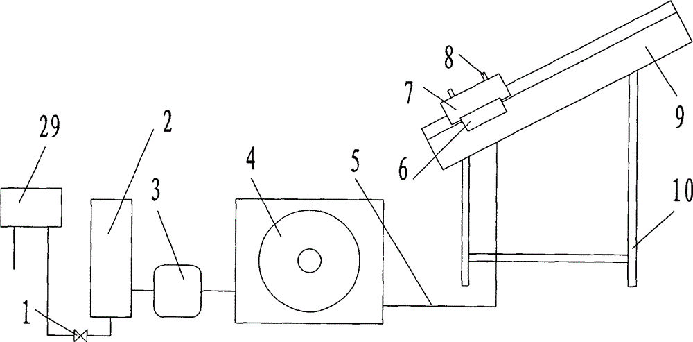
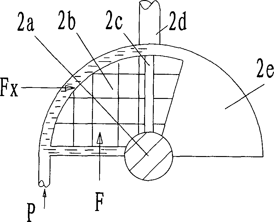
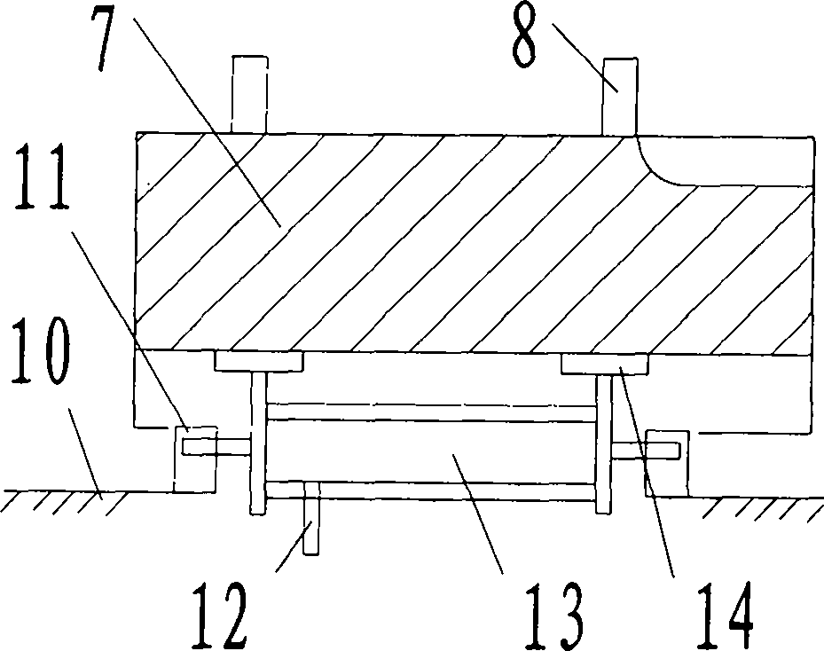
[0041] Embodiment 1: The aircraft launching device is provided by a flow control valve 1, a power generator 2, a gearbox 3, a hydraulic pump station 4, a hydraulic rubber hose 5, a hydraulic pusher 6, a bearing frame, a thruster, a guide rail 9, a frame 10 and mercury Device 29 is composed. The mercury provider 29 is connected to the bottom of the power generator 2 through the flow control valve 1 through the pipe, the output shaft of the power generator 2 is connected to the gearbox 3 shaft through the coupling, and the output shaft of the gearbox 3 is connected to the hydraulic pump through the coupling The input shaft of station 4 is connected, the hydraulic output port of hydraulic pump station 4 is connected with hydraulic hose 5, the other end of hydraulic hose 5 is connected with the inlet of hydraulic pusher 6, hydraulic pusher 6 is fixed on guide rail 9 or bracket 10, hydraulic pusher 6 The output end links to each other with the carrier, and the carrier is placed on ...

Embodiment 2

[0063] Embodiment 2: The hydraulic pusher includes a rack 15, a transmission hydraulic cylinder 16, and a flange 17. There is a flange 17 fixed on the support 10 below the cylinder body of the hydraulic cylinder, and the gear on the cylinder body meshes with the rack. The rack is fixed on the carrier frame 7.

[0064] Working principle: The hydraulic oil output from the hydraulic rubber hose enters the transmission hydraulic cylinder 16 to push the piston to move, the piston drives the gear to rotate, and the gear drives the rack to make the carrier 7 move in a straight line.

[0065] The outlet pipe valve 18 of the mercury provider is connected to a pressure regulating box 23 for adjusting and maintaining a stable mercury pressure, and the others are the same as in Embodiment 1.


PUM


Abstract

The invention discloses a control method for airplane launch and a device special for airplane launch, which belong to devices for launching objects. A mercury supplier of the device is connected with the bottom of a power generator by a flow control valve through a pipeline; the output shaft of the power generator is connected with the shaft of a transmission gear by a coupler; the output shaft of the transmission gear is connected with the input shaft of a hydraulic pump station by the coupler; the hydraulic output port of the hydraulic pump station is connected with a hydraulic rubber pipe; the other end of the hydraulic rubber pipe is connected with the inlet of a hydraulic pusher; the hydraulic pusher is fixed on a guide rail or a bracket; the output end of the hydraulic pusher is connected with a carrying frame; the carrying frame is arranged on the guide rail which is fixed by the bracket; a thruster is fixed on the carrying frame; and an airplane is fixed to the thruster. The invention has the advantage that: by lifting mercury in advance to store energy and releasing great power in the form of the internal energy of the mercury, the airplane can acquire an accelerated speed instantly on a track and be stably launched to fly into the sky. The energy is stored in the mercury in advance and released in the form of the internal energy of the mercury, so that the problem of generating large power output is solved.

Description

technical field [0001] The invention relates to a launcher, in particular to a special launcher for aircraft. Background technique [0002] At present, when the aircraft is ready to fly, it usually takes off first. The aircraft takes off using the aircraft's own engine to start slowly, and then slides forward on the runway to gradually accelerate. When the speed of the aircraft reaches the flight speed, the aircraft leaves the ground. fly to the sky. When the plane takes off, it needs a very long special runway for the plane, and at the same time, the plane will consume a lot of fuel, and only one plane can take off at a time. Contents of the invention [0003] The purpose of the present invention is to provide a special device for launching aircraft to solve the problem that a very long special runway for aircraft is needed when the aircraft takes off, and the aircraft consumes a large amount of fuel and can only take off one aircraft at a time. [0004] The object of t...

Claims


Application Information

Patent Timeline
Patent Type & Authority Patents(China)
IPC IPC(8): B64F1/04
Inventor 姜代红黄忠东韩成春孙荣军
Owner XUZHOU UNIV OF TECH
Why Eureka
Eureka Blog
Learn More