Local path planning method and system for unmanned vehicle

A technology for local path planning and unmanned vehicles, applied in vehicle position/route/height control, control/regulation systems, motor vehicles, etc., can solve problems such as uneven turning, achieve stable acceleration and speed changes, and improve stability performance, smooth running status

Active Publication Date: 2022-03-18
HENAN UNIVERSITY OF TECHNOLOGY
View PDF8 Cites 0 Cited by
  • Summary
  • Abstract
  • Description
  • Claims
  • Application Information

AI Technical Summary

Problems solved by technology

[0004] The existing technology has the problems of straight swing and uneven turning. The purpose of the present invention is to overcome the above-mentioned defects of the prior art and propose a local path planning method and system for unmanned vehicles.

Method used


Image

  • Local path planning method and system for unmanned vehicle
  • Local path planning method and system for unmanned vehicle
  • Local path planning method and system for unmanned vehicle

Examples


Embodiment 1

[0062] Embodiment 1 of the present invention proposes a local path planning method for unmanned vehicles. Specific steps are as follows:

[0063] First, establish a sports equation

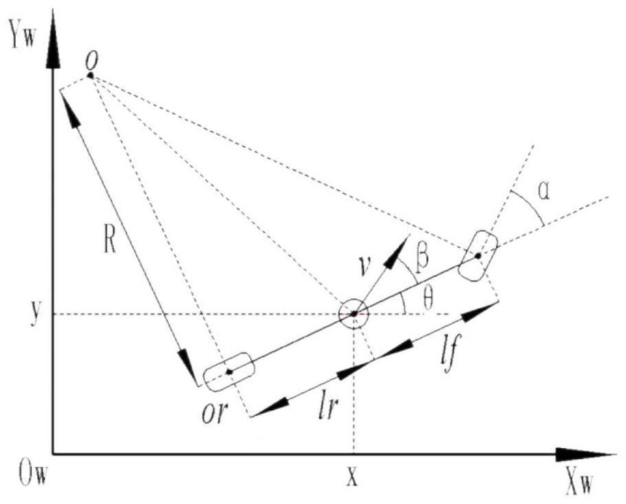
[0064] Such as figure 1 As shown, the world coordinate is X W O W Y W The base-sitting system is set to the rear axle center of the simplified operation model, X, Y is the coordinate of the vehicle in the world coordinate system, O is the instantaneous rotation center of the motion model, or the back wheel center, V is the vehicle rear axle center speed However, θ is the rope angle (navigation angle) of the vehicle, α is the front wheel virtual steering angle, and β is the steering angle at which R is the turn radius, the front wheel and the rear wheel to the vehicle centers are L. f And L r , L is the wheelbase, equal to L f And L r Sum.

[0065] From inhomatology,

[0066]

[0067] t Represents the current movement time, R min Indicates the minimum turn radius, ω is the front wheel corner speed.

...

Embodiment 2

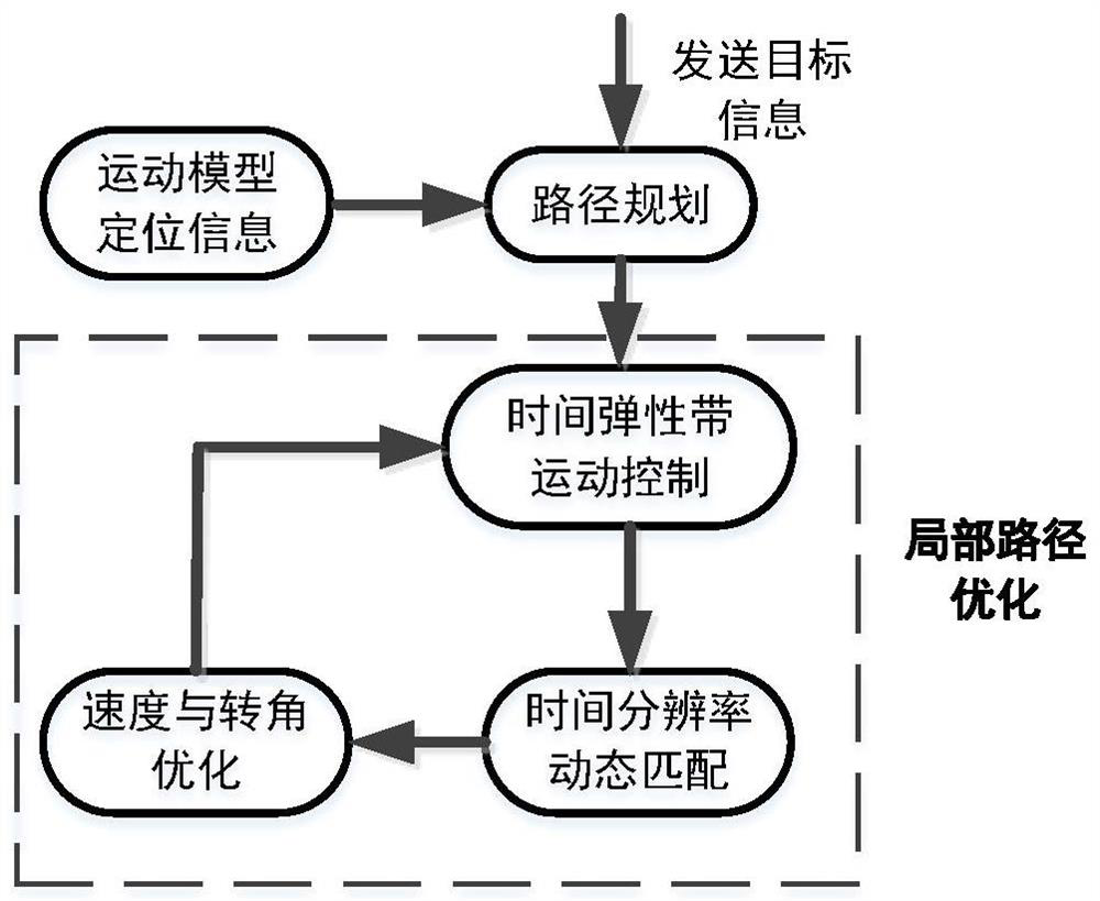
[0116] Embodiment 2 of the present invention proposes a local path planning system for driverless vehicles, based on the combined navigation sensor implementation, using the method of the first embodiment, including: motion model establishment module, positioning information acquisition module, cost Function establishment module and dynamic adjustment module; where

[0117] The motion model establishes a module for establishing a kinematic equation in the world coordinate system, and the speed and corner of the vehicle movement are independent, establish a motion model;

[0118] The positioning information acquisition module is configured to convert the data acquired by the combined navigation sensor to the navigation coordinate system based on real-time carrier phase dynamic differential techniques, providing positioning information for vehicle operation;

[0119] The cost function establishes a module for two aspects of time and bit posture, and establish a multi-objective cost ...


PUM


Abstract

The invention discloses a local path planning method and system for an unmanned vehicle, and the method is realized based on an integrated navigation sensor, and the method comprises the steps: 1) building a kinematics equation in a world coordinate system, and building a motion model by taking the speed and the rotation angle of the vehicle in motion as independent variables; 2) based on a real-time carrier phase dynamic difference technology, converting data acquired by the integrated navigation sensor into a navigation coordinate system, and providing positioning information for vehicle operation; step 3) from two aspects of time and pose, establishing a multi-objective cost function by implementing a weighted multi-objective optimization method; and 4) determining the running state of the vehicle, and fusing the time resolution parameter dtref to carry out dynamic adjustment so as to realize stable running of the vehicle. According to the method, the stability of the speed and the turning angle of the vehicle in the turning process is improved, the purpose of flexible and accurate movement of the vehicle at different curves is achieved, and the application range of the unmanned vehicle is expanded from the application angle.

Description

Technical field [0001] The present invention is in the field of driving technologies, path planning techniques, and vehicle control technology, and more particularly to a local path planning method and system for unmanned vehicles. Background technique [0002] Since smart vehicles with unmanned function can solve traffic accidents and atmospheric pollution caused by driving fatigue from many ways, smart unmanned vehicles have gradually become the focus of concern and research. From the perspective of development trends, unmanned driving will be an important development direction of the future. Since unison is involved in a huge industrial chain, we will not only promote the sustainable development of the automotive industry Green development processes also drive more investment and employment. Unmanned smart automobile technology can be divided into three parts, environmentally aware technology, intelligent decision technology, and control implementation technology. In a driver'...

Claims


Application Information

Patent Timeline
Patent Type & Authority Applications(China)
IPC IPC(8): G05D1/02
CPCG05D1/0221G05D1/0223G05D2201/0212Y02T10/40
Inventor 张涛张博强陈晨冯天培孙朋
Owner HENAN UNIVERSITY OF TECHNOLOGY
Why Eureka
Try Eureka