
Outer disk motor having barrier stator

A fence-type, stator technology, applied in the direction of magnetic circuit shape/style/structure, winding conductor shape/style/structure, electric components, etc., can solve the problem of uneven magnetic circuit, large and small output, uneven rotation, heat generation and energy consumption problems without proper answers, etc., to achieve the effect of improving energy conversion efficiency, smooth operation, and easy heat dissipation

Active Publication Date: 2019-08-16
SHENZHEN SHANXIANG INTELLIGENT TECH ENTERPRISE LLP
View PDF6 Cites 2 Cited by
  • Summary
  • Abstract
  • Description
  • Claims
  • Application Information

AI Technical Summary

Problems solved by technology

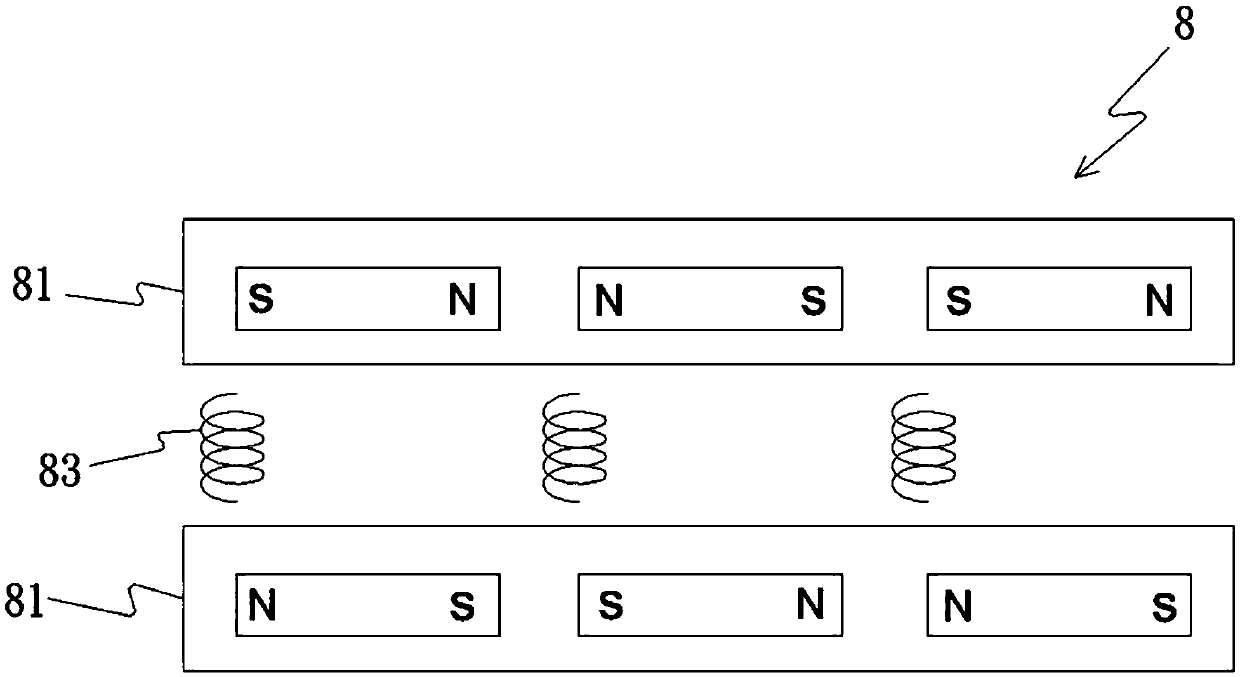
A kind of known disc generator 8, such as figure 2 As shown, although a motor structure with a disk-type outer rotor 81 is disclosed, there is no appropriate answer to the above-mentioned heat generation and energy consumption problems
In addition, if the number of permanent magnets and coils 83 is not properly matched, the magnetic circuit will not act uniformly, and in each action cycle, it may cause uneven rotation with large and small output

Method used


Image

  • Outer disk motor having barrier stator
  • Outer disk motor having barrier stator
  • Outer disk motor having barrier stator

Examples


Embodiment Construction

[0033] The aforementioned and other technical content, features and effects of the present invention will be clearly presented in the following detailed description of the preferred embodiments in conjunction with the accompanying drawings; in addition, in each embodiment, the same elements will be similar The label indicates.

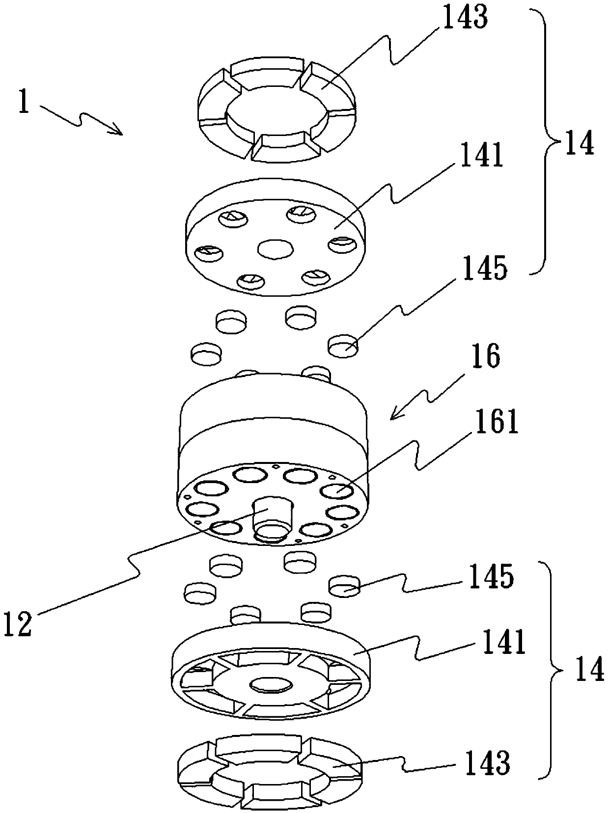
[0034] Please refer to the first preferred embodiment of an outer disk motor with a fence-type stator in the present invention Figures 3 to 6 As shown, the aforementioned outer disc motor 1 has a pivot 12 extending in an axial direction. For the convenience of description, the aforementioned axial direction is defined here as the up and down direction along the drawing, and two disc motors arranged parallel to each other The outer rotors 14 , each disc-type outer rotor 14 respectively include a disc body 141 and an even number of permanent magnets 143 , in this example, 6 permanent magnets 143 are taken as an example. In addition, the disk bodies 141...


PUM


Abstract

The present invention provides an outer disk motor having a barrier stator. The outer disk motor comprises a pivot shaft; a plurality of disc type outer rotors arranged in parallel, wherein each disctype outer rotor comprises a disc body and an even number of permanent magnets, the center of each disc body is vertically and fixedly arranged at the pivot shaft, the adjacent permanent magnets are arranged uniformly in a mode of homopolar opposition, the different magnetic poles of the permanent magnets of the disc type outer rotors are opposite to each other; a barrier stator comprising a plurality of strip-shaped iron cores which are parallel to the axial direction and are uniformly arranged and distributed at a round tube by taking the pivot shaft as a center, wherein the two poles of each strip-shaped iron core respectively correspond to the permanent magnets, and the number of the iron cores is greater than one time and less than two times of the number of the permanent magnets; andan enable controller configured to supply alternating current clock rate drive signals to allow each two adjacent clock rate drive signals to have uniform phase difference, wherein the sum of the phase differences of the barrier type stator is a non-zero integral multiple of 360 degrees.

Description

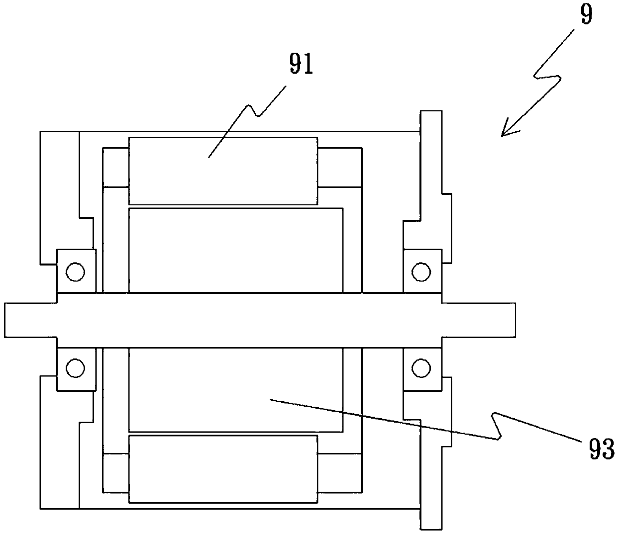
technical field [0001] An outer disk motor, in particular an outer disk motor with a fence stator. Background technique [0002] The common permanent magnet DC servo motor is to set the permanent magnet on the outer rotor, and set the armature coil on the core of the stator. Whether the current passes through the armature coil, it will generate heat due to resistance, or during the commutation process. It is difficult to dissipate the sudden heat when the current jump occurs in the middle; if it is applied to the direct drive system, the high heat at the rotor will be transferred to the drive shaft, and it will gradually cause the deformation of the drive shaft after long-term use; on the contrary, Such as figure 1 In the permanent magnet AC servo motor 9 shown, the stator with the armature coil 91 is arranged on the outer layer of the motor, and the permanent magnet 93 is arranged on the rotor at the core, so the heat dissipation is better and the power to volume ratio is ...

Claims


Application Information

Patent Timeline
IPC IPC(8): H02K16/00H02K16/02H02K1/27H02K1/12H02K1/18H02K3/28
CPCH02K1/12H02K1/187H02K1/2786H02K3/28H02K16/00H02K16/02
Inventor 黄思伦
Owner SHENZHEN SHANXIANG INTELLIGENT TECH ENTERPRISE LLP
Learn More