Automatic power test machine for ultra-thin heat pipe and working method thereof

An automatic power, ultra-thin heat pipe technology, applied in the direction of material thermal development, instrumentation, program control in sequence/logic controllers, etc., can solve the problems of difficult to simulate the gravity environment of heat pipes, mechanical damage of ultra-thin heat pipes, and high labor costs. Achieve the effect of improving test efficiency, saving labor costs and saving working time

CN110542704APending Publication Date: 2019-12-06SOUTH CHINA UNIV OF TECH +1
0 Cites 2 Cited by

Patent Information

Authority / Receiving Office
CN · China
Current Assignee / Owner
Publication Date
2019-12-06

Smart Images

  • Figure 1
    Figure 1
  • Figure 2
    Figure 2
  • Figure 3
    Figure 3
Patent Text Reader

Abstract

The invention discloses an automatic power test machine for an ultra-thin heat pipe and a working method thereof. The automatic power test machine comprise a rack, a material lifting mechanism, a material height detection mechanism, a feeding mechanism, a test fixture mechanism, a program-controlled direct-current power supply and a PLC (programmable logic controller); the material height detection mechanism is provided with a trough, a material sensor and a photoelectric sensor, the material sensor is used for sensing whether materials exist in the trough, the photoelectric sensor is used fordetecting the height of the heat pipe in the trough, and the material lifting mechanism is used for maintaining the heat pipe in the trough at an appointed height; the feeding mechanism is arranged on a substrate, the feeding mechanism is provided with a vacuum sucker, and the feeding mechanism is used for realizing feeding and blanking of the heat pipe through the vacuum sucker; the test fixturemechanism is provided with a heat pipe placing block and a temperature sensing block, the heat pipe placing block is provided with a heating block and a cooling block, the feeding mechanism is used for placing the heat pipe on the heat pipe placing block through the vacuum sucker, one end of the heat pipe is in contact with the heating block, the other end of the heat pipe is in contact with thecooling block, the temperature sensing block is electrically connected with a temperature acquisition card, and the temperature sensing block is used for acquiring temperatures at two ends of the heatpipe.
Need to check novelty before this filing date? Find Prior Art

Description

technical field

[0001] The invention relates to the technical field of heat pipe testing, in particular to an ultra-thin heat pipe automatic power testing machine and a working method thereof. Background technique

[0002] Heat pipe is a kind of high-efficiency heat conduction element based on the principle of vapor-liquid phase transition, which is widely used in the field of heat dissipation of electronic products. With the continuous improvement of the chip integration of mobile phones and other electronic products, the power consumption of chips will inevitably increase. Therefore, the use of heat pipes for thermal management of mobile phones and other electronic products has become an effective solution. However, the internal space of electronic products such as mobile phones and tablets is very limited, so it is necessary to use ultra-thin heat pipes after flattening as heat transfer elements. There are three main criteria for judging the performance of a heat pipe: h...

Examples

Embodiment

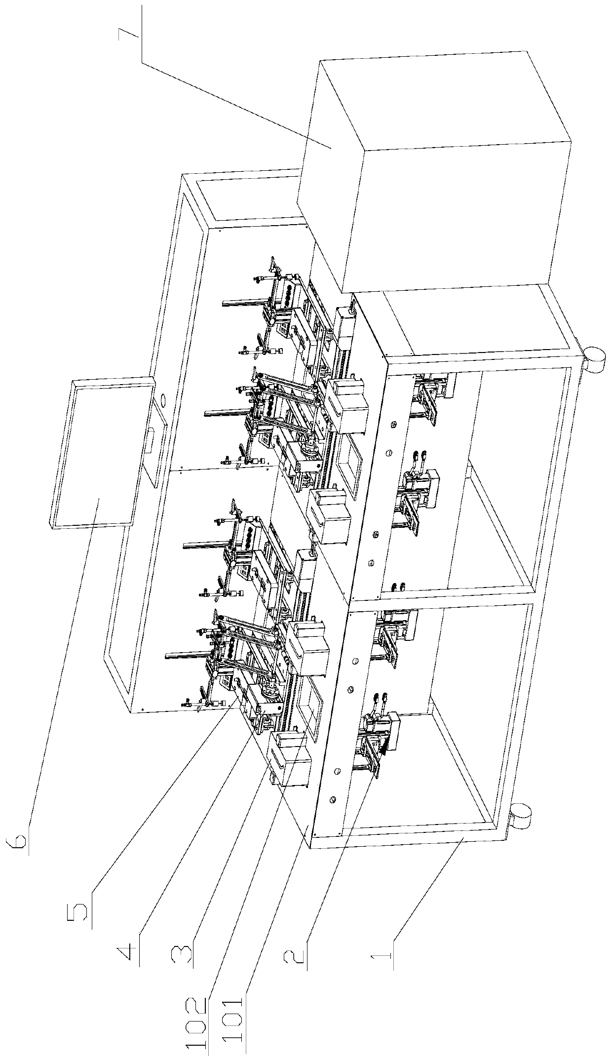
[0029] Such as figure 1 As shown, this embodiment provides an automatic power testing machine for ultra-thin heat pipes, including a frame 1, a material lifting mechanism 2, a material height detection mechanism 3, a feeding mechanism 4, a test fixture mechanism 5, a program-controlled DC power supply, a computer 6, and a constant temperature Water tank 7, temperature acquisition card and PLC controller.

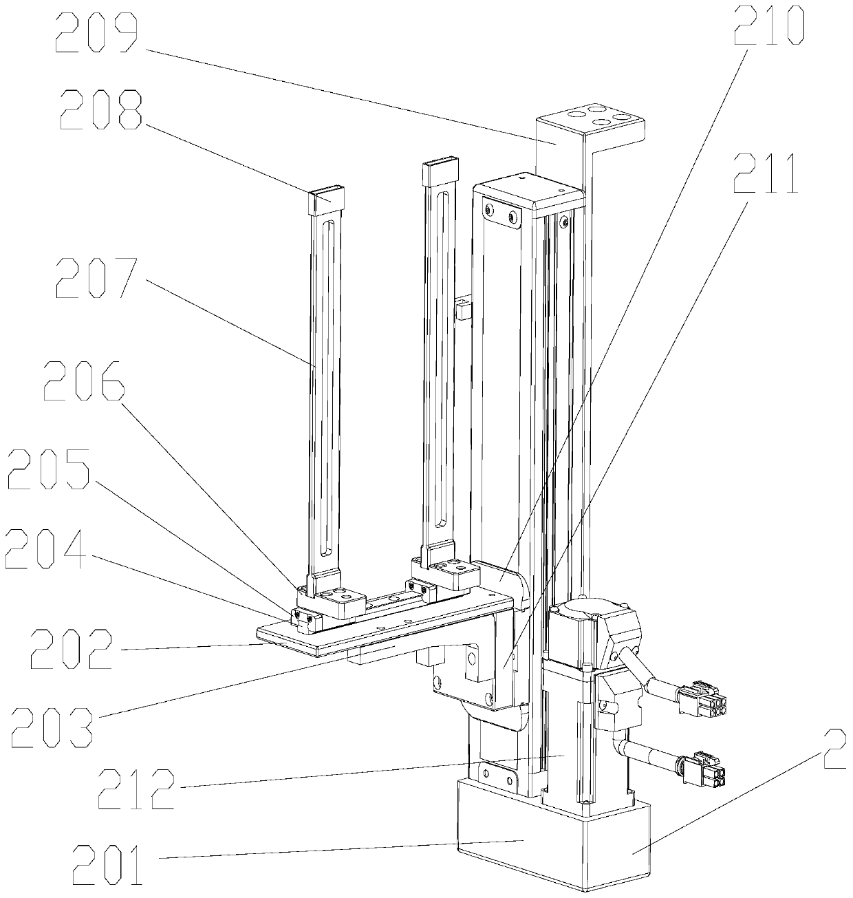
[0030] Such as figure 1 with figure 2 As shown, the frame is provided with a base plate 101, the base plate is provided with a groove 102 for placing qualified products and unqualified products, and the material lifting mechanism includes a vertical module 201, a support column bottom plate 202, a reinforcing rib 203, and a horizontal guide rail 204 , horizontal guide rail slider 205, ejector pin bottom plate 206, ejector pin 207, magnet replacement block 208, material placement back plate 209, vertical module slider 210, rib mounting block 211 and vertical motor 212, mat...