Vehicle driven under assistance of gravity

A gravity and vehicle technology, which is applied to vehicle components, wheels, power plants, etc., can solve the problems of short battery energy mileage, time-consuming battery charging, and inconvenient car charging, and achieve small deformation, energy saving, and load reduction. Effect

Inactive Publication Date: 2018-11-16
福建省连江乐鑫林业开发有限公司
View PDF4 Cites 0 Cited by
  • Summary
  • Abstract
  • Description
  • Claims
  • Application Information

AI Technical Summary

Problems solved by technology

[0003] Now new energy vehicles include solar vehicles, hydrogen energy vehicles, compressed air vehicles, electric vehicles and vehicles using other energy sources. At present, the vehicles that our country supports and promotes economically are mainly electric vehicles. Electric vehicles have no exhaust pollution and are environmentally friendly. It has made a positive contribution, but the biggest disadvantage of electric vehicles is that the energy provided by the battery has a short cruising range, and the charging of the battery is time-consuming, and charging piles are not installed in urban communities, and charging piles are not yet popular in towns and villages. Makes car charging extremely inconvenient
[0004] So far, the national research on the use of gravity to drive vehicles or gravity as an available energy source has not been put on the agenda or has not been included in the research plan, and the energy saving of automobiles is often small, and the energy saving is extremely limited

Method used


Image

  • Vehicle driven under assistance of gravity
  • Vehicle driven under assistance of gravity
  • Vehicle driven under assistance of gravity

Examples


Embodiment 1

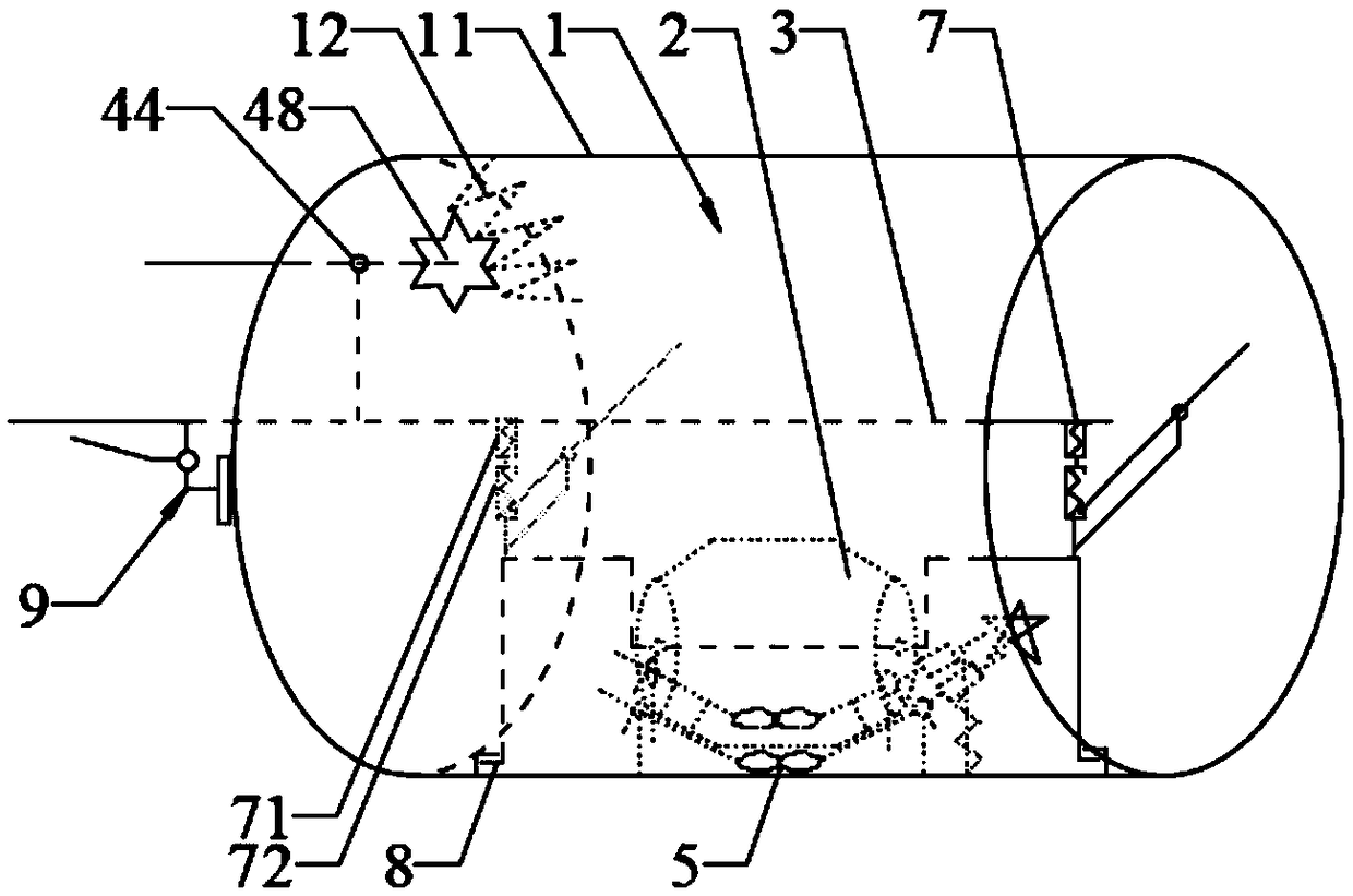
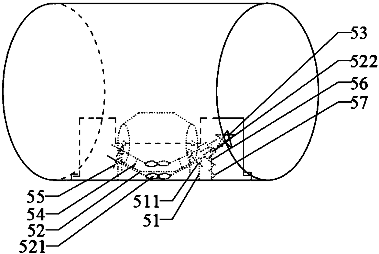
[0092] Please refer to Figure 1 to Figure 4 As shown, a vehicle utilizing gravity-assisted driving includes an outer wheel 1, an inner wheel 2, a chassis 3, an electric drive device 4, a gravity-assisted driving device 5 and a gravity transmission device 6;

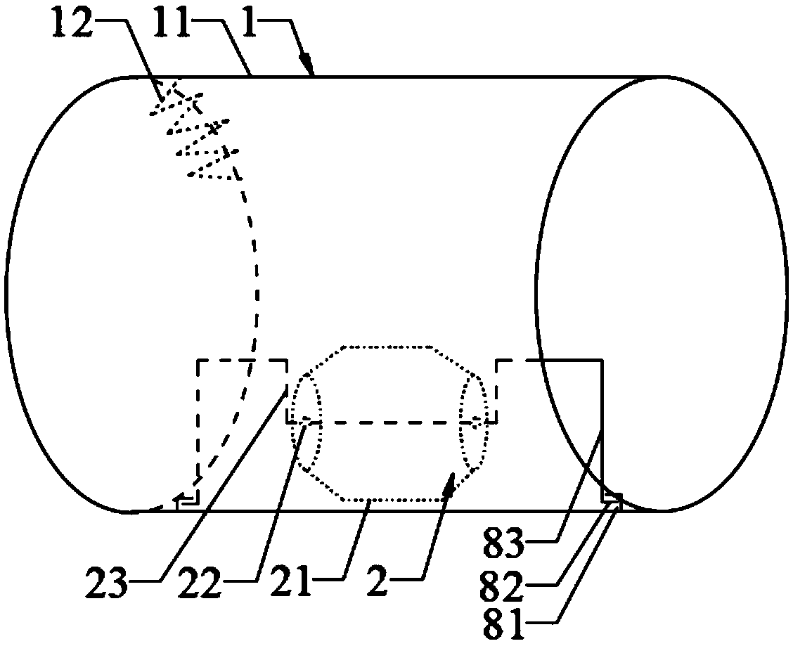
[0093]Described outer wheel 1 comprises hard wheel 11 and hard wheel 11 internal teeth 12, and described hard wheel internal tooth 12 is positioned at one end of hard wheel 11 and is distributed along the inner circumference of hard wheel 11; Described inner wheel 2 comprises bearing wheel 21, bearing bearing 22 and load-bearing shaft 23, the load-bearing wheel 21 is located in the middle part of the inner side of the hard wheel 11, the end face of the load-bearing wheel 21 is provided with a central through hole, the load-bearing bearing 22 is arranged at the two ends of the central through-hole, and the load-bearing shaft 23 passes through the central through hole and is connected with load-bearing bearing 22, and the ...

Embodiment 2

[0098] Please refer to Figure 7 As shown, it is the same as other structures of the gravity-assisted vehicle in Embodiment 1, the difference is that the electric drive device 4 can be:

[0099] The electric drive device 4 includes a speed-regulating motor 41 and a drive gear 48 driven by the speed-regulating motor 41, and the drive gear 48 meshes with the hard wheel internal teeth 12;

[0100] Also comprise motor shaft gear 42, rotating shaft 43, rotating shaft bearing 44, rotating shaft bearing block 45, rotating shaft gear 46 and shaft transmission gear 47, described motor shaft gear 42 is arranged on the motor shaft of speed regulating motor 41, so The rotating shaft 43 is arranged on the chassis 3 through the rotating shaft bearing 44 and the rotating shaft bearing seat 45. The rotating shaft gear 46 is arranged on the rotating shaft 43 and meshes with the motor shaft gear 42. The gear of the shaft transmission gear 47 The shaft is arranged on the chassis 3 and the shaft...

Embodiment 3

[0102] Please refer to Figure 5 with Image 6 As shown, it is the same as other structures of the gravity-assisted vehicle in Embodiment 2, the difference is that the gravity-assisted vehicle also includes a shock absorber 7, and the shock absorber 7 is arranged on the bearing shaft 23 and the chassis 3 Between, the shock absorber 7 includes a gas spring shock absorber 71 and a vibration energy utilization device 72, the upper end of the gas spring shock absorber 71 is connected to the chassis 3, and the lower end of the gas spring shock absorber 71 is connected to the vibration The upper end of the energy utilization device 72 is connected, and the lower end of the vibration energy utilization device 72 is connected to the bearing shaft 23;

[0103] Described vibration energy utilization device 72 comprises damping spring 721, the spring cover 722 with slide groove, damping rotating rod 723, damping rotating rod bearing 724 and damping rotating rod bearing shaft 725, descri...


PUM


Abstract

The invention relates to the technical field of energy-saving vehicle manufacturing, in particular to a vehicle driven under assistance of a gravity. The vehicle driven under the assistance of the gravity comprises an external wheel, an internal wheel, a chassis, an electric driving device, a gravity assisted driving device and a gravity transmission device; the external wheel comprises a hard wheel and hard wheel internal teeth; the hard wheel internal teeth are positioned at one end of the hard wheel and distributed along the circumference of the internal side of the hard wheel; the internalwheel comprises a load-bearing wheel, load-bearing bearings and a load-bearing shaft; the load-bearing wheel is positioned at the middle part of the internal side of the hard wheel; a central throughhole is formed in the end surface of the load-bearing wheel; the load-bearing bearings are arranged at the two ends of the central through hole; the load-bearing shaft penetrates through the centralthrough hole and is connected with the load-bearing bearings; and the two ends of the load-bearing shaft are connected with the chassis. The vehicle driven under the assistance of the gravity has thebeneficial effects that the structural design is simple, the operation is convenient, the gravity force hindering wheel running can be utilized as a driving force for driving the vehicle to advance sothat energy needed by the vehicle during running is saved, a purpose of greatly saving energy can be achieved, and moreover, the endurance can also be enhanced.

Description

technical field [0001] The invention relates to the technical field of energy-saving vehicle manufacturing, in particular to a vehicle driven by gravity. Background technique [0002] Gravity energy is free energy available anytime and anywhere, and it can be applied in automobiles and other fields one day earlier. It can not only save a large amount of oil, automobiles and other import expenses, but also reduce the damage to the earth caused by oil mining and combustible ice mining. Moreover, it will greatly promote the development of a powerful country and human beings. [0003] Now new energy vehicles include solar vehicles, hydrogen energy vehicles, compressed air vehicles, electric vehicles and vehicles using other energy sources. At present, the vehicles that our country supports and promotes economically are mainly electric vehicles. Electric vehicles have no exhaust pollution and are environmentally friendly. It has made a positive contribution, but the biggest disa...

Claims


Application Information

Patent Timeline
Patent Type & Authority Applications(China)
IPC IPC(8): B60K8/00B60B19/00F03G3/00
CPCB60K8/00B60B19/00F03G3/00
Inventor 柯玉铸
Owner 福建省连江乐鑫林业开发有限公司
Why Eureka
Try Eureka