
Artificial light source generator

A technology of artificial light sources and generators, applied in the direction of electric light sources, refractors, reflectors, etc., can solve the problems of loss of overall uniformity and achieve good lighting uniformity

Active Publication Date: 2011-08-17
ALL REAL TECH
View PDF0 Cites 0 Cited by
  • Summary
  • Abstract
  • Description
  • Claims
  • Application Information

AI Technical Summary

Problems solved by technology

In addition, if individual components shift position, resulting in a loss of overall uniformity, it must be readjusted

Method used


Image

  • Artificial light source generator
  • Artificial light source generator
  • Artificial light source generator

Examples


Embodiment Construction

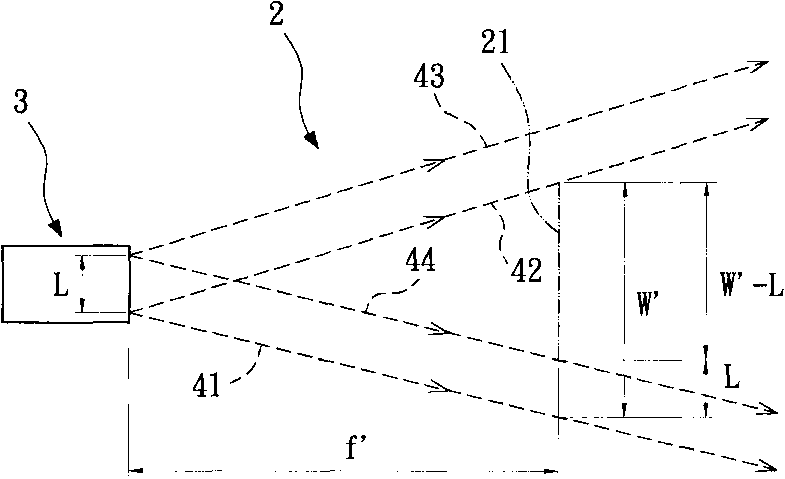
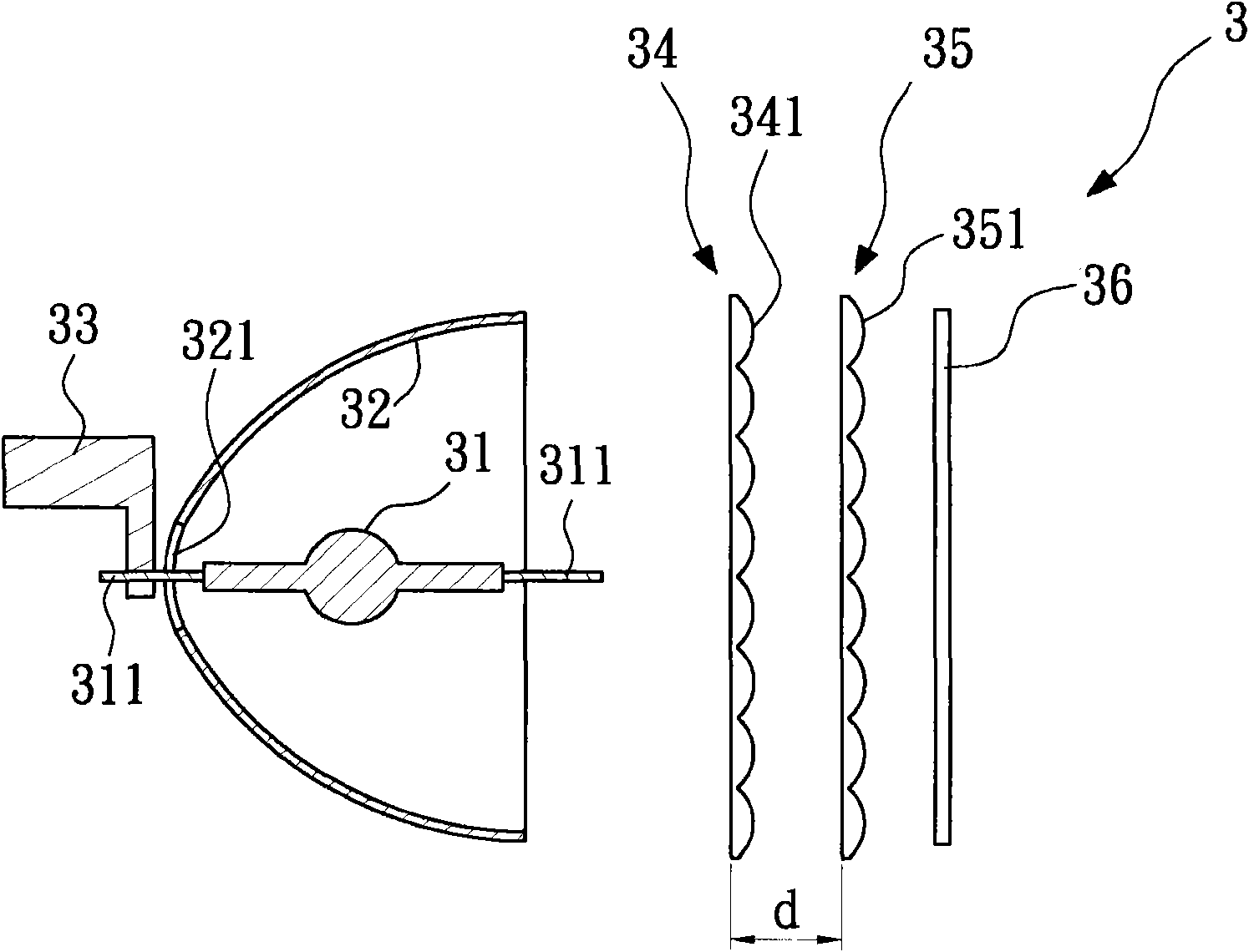
[0021] Please see figure 2 and image 3 , shows a schematic diagram of the artificial light source generator and its light-emitting group according to the first embodiment of the present invention. The artificial light source generator 2 of the present invention can be used indoors to simulate sunlight to test the solar cell module to obtain its relevant product characteristics, but it can be understood that the artificial light source generator 2 of the present invention can also be applied to other products that require place of light. The artificial light source generator 2 includes at least one light emitting group 3 and a projection plane 21 . see image 3 , the light emitting group 3 includes a light source 31 , a parabolic mirror 32 , a support base 33 , a first lens array 34 , a second lens array 35 and a filter 36 .

[0022] The light source 31 is used to generate light. In this embodiment, the light source 31 is a xenon lamp, which includes two terminal electro...


PUM


Abstract

The invention relates to an artificial light source generator, which comprises at least one light emitting set and a projection plane. The light emitting set comprises a light source, a parahboloidal mirror, a supporting seat, a first lens array and a second lens array. The light source is positioned on a focal point of the parahboloidal mirror so that lights generated by the light source are emitted out through the parahboloidal mirror along a parallel direction. The supporting seat is used for supporting the light source. The first lens array has multiple first lens units, each of which hasa first focal length. The second lens array has multiple second lens units; and the distance between the second lens array and the first lens array is 0.5-1.5 times larger than the first focal distance. The projection plane is spaced with a proper distance from the light emitting set so that the lights penetrating through each second lens unit all cover the whole projection plane. Therefore, the projection plane has the advantage of excellent illumination uniformity.

Description

[0001] This application is a divisional application of the invention patent application No. 200810168237.5 and the invention title is "Artificial Light Source Generator". technical field [0002] The invention relates to an artificial light source generator, in particular to an artificial light source generator capable of simulating a large area of ​​natural light. Background technique [0003] As the issues of environmental protection and energy saving are getting more and more attention, solar cell modules are gradually developing vigorously. However, one of the major problems faced after the solar cell module is manufactured is testing. Since the natural light (sunlight) will be strong or weak during the day, it is unstable and cannot be controlled by human means, so it is usually not to move the manufactured solar cell module outside for testing, the general test method It uses artificial light sources indoors to simulate sunlight to obtain product characteristics relat...

Claims


Application Information

Patent Timeline
Patent Type & Authority Applications(China)
IPC IPC(8): F21S2/00F21V7/06F21V5/04
Inventor 郭钟亮
Owner ALL REAL TECH
Learn More