
Electrochemical NMR in situ quantitative detection electrolytic cell with grid-like working electrode structure

A working electrode and nuclear magnetic resonance technology, which is applied to the electrochemical variables of materials and the analysis of nuclear magnetic resonance, can solve the problems of easy falling off, shortening the service life of electrodes, and reducing the adhesion between electrodes and glass, so as to increase thickness and prolong Effect of service life and improvement of adhesion

Inactive Publication Date: 2016-05-25
XIAMEN UNIV
View PDF3 Cites 0 Cited by
  • Summary
  • Abstract
  • Description
  • Claims
  • Application Information

AI Technical Summary

Problems solved by technology

However, both theoretical simulation calculations and experimental results show that even though the thickness of the metal film electrode is much smaller than the skin depth, due to the special cylindrical structure, it still has a strong shielding effect on the radio frequency field, thus destroying the radio frequency field around the working electrode Uniformity, which adversely affects the detection of NMR signals
In addition, the adhesion between the thin membrane electrode and the glass is reduced, and it is easy to fall off, reducing the service life of the electrode

Method used


Image

  • Electrochemical NMR in situ quantitative detection electrolytic cell with grid-like working electrode structure
  • Electrochemical NMR in situ quantitative detection electrolytic cell with grid-like working electrode structure
  • Electrochemical NMR in situ quantitative detection electrolytic cell with grid-like working electrode structure

Examples


Embodiment Construction

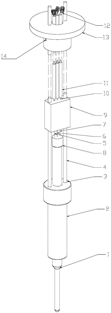
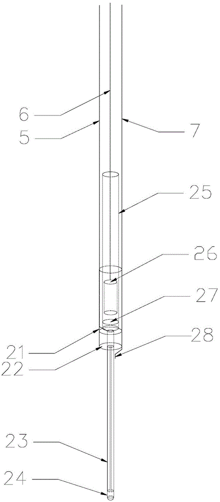
[0025] see Figure 1~6 , the embodiment of the present invention is provided with electrolytic cell body 1, sample tube rotor 2, connecting rod 4, electrode adapter plug 9, coaxial cable 11, fixed table 13, working electrode 23, auxiliary electrode 26, reference electrode 28, The first nuclear magnetic sample tube 21 , the second nuclear magnetic sample tube 24 , the third nuclear magnetic sample tube 25 , the fourth nuclear magnetic sample tube 31 , and the fifth nuclear magnetic sample tube 32 .

[0026] The top of the electrolytic cell body 1 is affixed to the bottom of the sample tube rotor 2, and the sample tube rotor 2 is provided with a connecting hole 3 for fixing the connecting rod 4, and the bottom end of the connecting rod 4 is connected with the connecting hole 3, and is located in the electrolytic cell. The working electrode 23, auxiliary electrode 26, and reference electrode 28 in the cell body 1 pass through the sample tube cap arranged on the top of the sample ...


PUM

PropertyMeasurementUnit
diameteraaaaaaaaaa
diameteraaaaaaaaaa

Abstract

An electrochemical nuclear magnetic resonance in situ quantitative detection electrolytic tank of a grid-shaped working electrode structure relates to an electrochemical electrolytic tank and is provided with a tank body, a sample tube rotor, a connection rod, an electrode adapter plug, a fixing platform, three electrodes and nuclear magnetic sample tubes. The top of the tank body is fixedly connected at the bottom of the ample tube rotor. The three electrodes penetrate through a sample tube cap arranged at the top of the sample tube rotor through outgoing wires and are connected onto a coaxial cable through a metal pin disposed in the electrode adapter plug, the top of the coaxial cable is fixed on the fixing platform disposed at the top of the connection rod, and the coaxial cable is externally connected with an electrochemical work station. The five nuclear magnetic sample tubes are arranged in the tank body, the second nuclear magnetic sample tube is coaxially fixed in the first nuclear magnetic sample tube, the area between the second nuclear magnetic sample tube and the fifth nuclear magnetic sample tube constitutes a working electrode electrolytic reaction chamber, a porous glass core is embedded below the third nuclear magnetic sample tube and an auxiliary electrode reaction chamber is formed, and an isolation reaction chamber is formed between the third nuclear magnetic sample tube and the first nuclear magnetic sample tube.

Description

technical field [0001] The invention relates to an electrochemical electrolytic cell, in particular to an electrochemical nuclear magnetic resonance in-situ quantitative detection electrolytic cell with a grid-like working electrode structure. Background technique [0002] In electrochemistry, the thermodynamics and kinetics of the adsorption process of reactive molecules under the action of an electric field at the solid / liquid interface, and the catalytic reactions (oxidation, reduction) of reactive molecules can be obtained by changing the electrode Fermi level consistent with the electron acceptor orbital energy information about the process and the interaction with the electrode surface. The research on the solid / liquid interface generally uses electrical signals (potential, current) as the means of excitation and detection to obtain various average information of the electrode / electrolyte solution interface and the electrode surface, and then uniquely analyze various e...

Claims


Application Information

Patent Timeline
Patent Type & Authority Patents(China)
IPC IPC(8): G01N27/28G01N27/30G01N24/08
Inventor 倪祖荣陈忠郑振耀孙惠军孙世刚
Owner XIAMEN UNIV
Learn More