
led light source module and its led street lamp

A technology of LED light source and PCB board, applied in the direction of light source, electric light source, semiconductor devices of light-emitting elements, etc., can solve the problems of increasing the use cost of LED street lamps, low one-time success rate of welding light source, and increasing the difficulty of design, etc. Comprehensive utilization efficiency, saving development investment cost, good effect of waterproof and dustproof environment

Active Publication Date: 2016-06-15
CECEP LATTICELIGHTING
View PDF5 Cites 0 Cited by
  • Summary
  • Abstract
  • Description
  • Claims
  • Application Information

AI Technical Summary

Problems solved by technology

[0002] At present, the design of LED street lamps usually imitates the design ideas of traditional street lamps, and multiple LED lamp beads are assembled in a module, so that the products produced by different manufacturers are not universal and interchangeable, resulting in the replaceability of LED street lamps. Poor performance and high maintenance costs indirectly increase the cost of using LED street lamps; secondly, this structure also needs to be redesigned for dustproof and waterproof lamps used in outdoor conditions, which increases the difficulty of design; thirdly, the structure Indirect contact thermal resistance is high, junction temperature is high, heat dissipation efficiency is low, and the heat released by the chip cannot be effectively exported and dissipated, resulting in low light efficiency, large light decay, and short life of LED lighting fixtures, which cannot meet lighting needs
Finally, the consistency between the light sources of LED street lamps designed in this way is relatively poor, and the one-time success rate of welding light sources is relatively low, which is not conducive to mass production

Method used


Image

  • led light source module and its led street lamp
  • led light source module and its led street lamp
  • led light source module and its led street lamp

Examples


Embodiment Construction

[0026] The present invention will be further described below in conjunction with the accompanying drawings of the description.

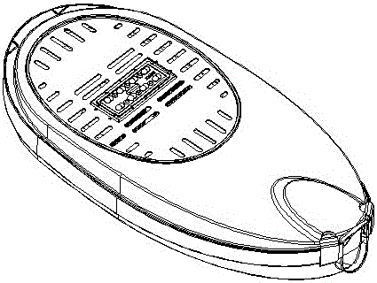
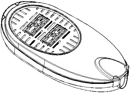
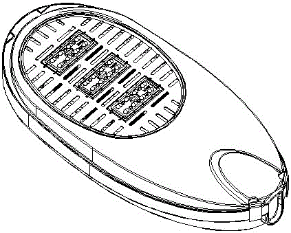
[0027] see figure 1 with figure 2 , a LED light source module, consisting of a lens cover 2, a lens 1 arranged in an array on the lens cover 2, a sealing ring 3, a PCB board 5, an LED light source 4 arranged on the PCB board 5, and a heat sink 6. The fins 7 arranged on the back of the heat sink 6, the rubber plug 9, the pressure plate 10, the concave hole 11 and the through hole 12 arranged in the middle of the heat sink 6 are composed; the fins 7 are provided with a fin gap 8 in the vertical direction, The LED light source 4 array is arranged on the PCB board 5, and the PCB board 5 is installed on the front of the heat sink 6, and the heat conduction paste is coated between the PCB board 5 and the heat sink 6, and the sealing ring 3 closely surrounds the edge of the PCB board 5 , the lens surface cover 2 is covered on the PCB board 5, and the ele...


PUM


Abstract

The invention discloses an LED (Light Emitting Diode) light source module and an LED streetlamp using the same. The LED light source module consists of a lens surface cover, lenses which are arranged on the lens surface cover, a sealing ring, a PCB (Printed Circuit Board), LED light sources which are arranged on the PCB, a heat sink, fins which are arranged on the back surface of the heat sink, a rubber plug, a pressing plate, a concave hole and a through hole which is formed in the middle of the heat sink. Fin gaps are arranged in the vertical direction of the fins. The PCB is installed on the front surface of the heat sink. Heat transfer paste is coated between the PCB and the heat sink. The sealing ring closely surrounds the edge of the PCB. The lens surface cover covers the PCB. The rubber plug blocks the concave hole and is tightly fixed on the back surface of the heat sink through the pressing plate. The LED light source module has the advantages that the weight is light, the size is small, the module is integrated with heat dissipating, light distribution and dustproof and waterproof performances, LED streetlamps with different power and shapes can be flexibly formed when the LED light source module is combined with the housing and the driving circuit of the traditional streetlamp, and the LED light source module is applicable to the fields of LED streetlamps, LED tunnel lamps, LED projection lamps and the like.

Description

technical field [0001] The invention belongs to the technical field of semiconductor lighting, and specifically relates to an LED light source module suitable for various LED street lamps and an LED street lamp manufactured using the LED light source module. Background technique [0002] At present, the design of LED street lamps usually imitates the design ideas of traditional street lamps, and multiple LED lamp beads are assembled in a module, so that the products produced by different manufacturers are not universal and interchangeable, resulting in the replaceability of LED street lamps. Poor performance and high maintenance costs indirectly increase the cost of using LED street lamps; secondly, this structure also needs to be redesigned for dustproof and waterproof lamps used in outdoor conditions, which increases the difficulty of design; thirdly, the structure The indirect contact thermal resistance is high, the junction temperature is high, and the heat dissipation e...

Claims


Application Information

Patent Timeline
Patent Type & Authority Patents(China)
IPC IPC(8): F21S8/00F21V5/04F21V29/00F21V31/00F21W131/103F21Y115/10F21V29/50F21V29/74F21V29/89
Inventor 张志海吴新慧曾平
Owner CECEP LATTICELIGHTING
Learn More