Device for measuring flow and flow velocity of drainage pipeline synchronously

A flow velocity measuring device and a technology for drainage pipes, which are applied in the field of water supply and drainage, can solve the problems that the process of changing the flow rate of sanitary appliances with time cannot be reflected, the outflow characteristics of sanitary appliances cannot be reflected, and the instantaneous flow velocity of water flow cannot be truly reflected. Easy to install and operate, not limited by site, easy to install

Inactive Publication Date: 2011-08-17
北京建筑工程学院
View PDF3 Cites 12 Cited by
  • Summary
  • Abstract
  • Description
  • Claims
  • Application Information

AI Technical Summary

Problems solved by technology

These two flow measurement methods have a common feature that the obtained flow value is the average flow, not the instantaneous flow value, which cannot reflect the time-varying process of the outflow of the sanitary ware in a drainage process, and cannot reflect the real flow of the sanitary ware. outflow characteristics
[0004] Similarly, the method of measuring the average flow velocity between sections also has the same disadvantages as the above-mentioned method of flow measurement. It also obtains the average flow velocity by calculating the time of water flowing between two sections, which cannot truly reflect the instantaneous time when the water flows through a certain section. The flow velocity cannot reflect the flow velocity distribution of the water flow in the pipeline

Method used


Image

  • Device for measuring flow and flow velocity of drainage pipeline synchronously
  • Device for measuring flow and flow velocity of drainage pipeline synchronously

Examples


Embodiment Construction

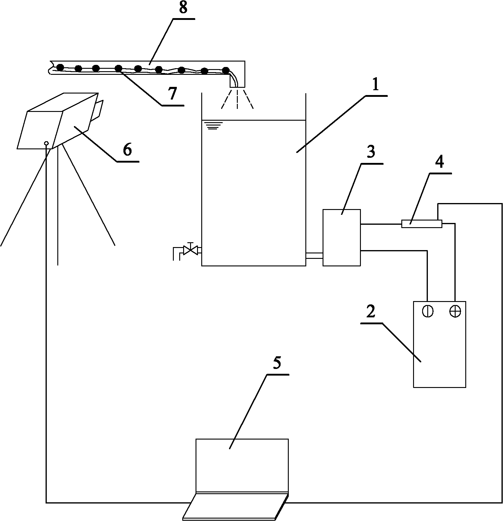
[0017] For a preferred embodiment of the present invention, see figure 1 , the corresponding drainage pipeline flow and flow velocity synchronous measurement device includes a flow measurement device, a flow velocity measurement device and a computer,

[0018] The corresponding flow measuring devices include:

[0019] The shock-reducing metering water tank 1 has a water injection port for receiving the water discharged from the predetermined drainage pipe 8 at the upper end, and a small hole at the lower end;

[0020] A stabilized power supply 2, used to provide a predetermined voltage for the differential pressure transmitter 3;

[0021] The differential pressure transmitter 3 communicates with the small hole at the lower end of the shock-reducing metering tank 1 through a hose, and is used to generate a corresponding current according to the pressure change when the water level of the shock-reducing metering tank 1 changes;

[0022] The A / D data acquisition card 4 is used ...


PUM


Abstract

The invention relates to a device for measuring a flow and a flow velocity of a drainage pipeline synchronously. A water inlet is formed at the upper end of an impact-relief measuring water tank and a small hole is formed at the lower end of the impact-relief measuring water tank; a stabilized voltage supply is used for providing voltage for a differential pressure transducer; the differential pressure transducer is connected with the small hole at the lower end of the impact-relief measuring water tank through a hose and is used for generating a corresponding current according to the change of pressure intensity; an analog/digital (A/D) data acquisition card is used for acquiring the voltage of the two ends of a resistor which is connected with the differential pressure transducer, converting voltage signals into digital signals and sending the digital signals to a computer; a vidicon is used for taking a picture of a reference object moving with water flow in the drainage pipeline and transmitting the taken picture to the computer in real time; and the computer is used for receiving the real-time picture which is transmitted by the vidicon and computing the flow velocity of water in the drainage pipeline through an image acquisition frequency and a displacement distance of the image in each frame, and receiving the digital signals sent by the A/D data acquisition card and computing the flow of water in the drainage pipeline. The invention is applicable for measuring the drainage flow and the drainage flow velocity of the sanitary ware and the horizontal drainage pipeline in a building.

Description

technical field [0001] The invention relates to a flow and flow velocity measuring device, which is suitable for measuring the flow and flow velocity of drainage from sanitary appliances in buildings, and belongs to the technical field of water supply and drainage. Background technique [0002] With the increasing shortage of water resources, it is imperative to save water for sanitary appliances. In order to study the water-saving potential of sanitary appliances, it is necessary to study and analyze the hydraulic characteristics of the outflow, and the flow rate and flow velocity are the two most important characteristic indicators in the hydraulic characteristics. At present, the traditional flow measurement devices mainly include volumetric measurement devices and mass method measurement devices; the traditional flow velocity measurement methods are mainly the average flow velocity measurement method between sections. [0003] Both volumetric flow measuring devices and ...

Claims


Application Information

Patent Timeline
Patent Type & Authority Applications(China)
IPC IPC(8): G01F1/56G01P5/00
Inventor 吴俊奇张雅君翟立晓王文海韩芳
Owner 北京建筑工程学院
Why Eureka
Try Eureka