Stereo-projection system

A technology of stereoscopic projection and stereoscopic light source, which is applied in the field of optical instruments, can solve the problems of not being able to significantly improve the light intensity utilization rate, low light intensity utilization rate, and poor imaging quality, and achieve the best image restoration effect, high utilization rate, and conversion efficiency consistent effect

Inactive Publication Date: 2012-07-25
XIAN ZHONGKE JINGXIANG PHOTOELECTRIC SCI & TECH
View PDF1 Cites 0 Cited by
  • Summary
  • Abstract
  • Description
  • Claims
  • Application Information

AI Technical Summary

Problems solved by technology

The light intensity utilization rate of the projection display device is low, generally not more than 10%, and the image quality is poor when the power of the natural light source 10 is fixed.
[0006] In the Chinese patent application with application number 200910172326.1, aspherical lenses and cylindrical lenses are used to shape the light beam of the light source before transmission, so that the shaped light spot matches the length and width of LCOS, which improves the utilization of light intensity to a certain extent. rate, but its overall structure is similar to figure 1 The structure in is similar, but one of the polarized light is still used for imaging, and the light intensity utilization rate cannot be significantly improved.

Method used


Image

  • Stereo-projection system
  • Stereo-projection system
  • Stereo-projection system

Examples


Embodiment Construction

[0032] In order to make the above objects, features and advantages of the present invention more obvious and comprehensible, specific implementations of the present invention will be described in detail below in conjunction with the accompanying drawings and embodiments.

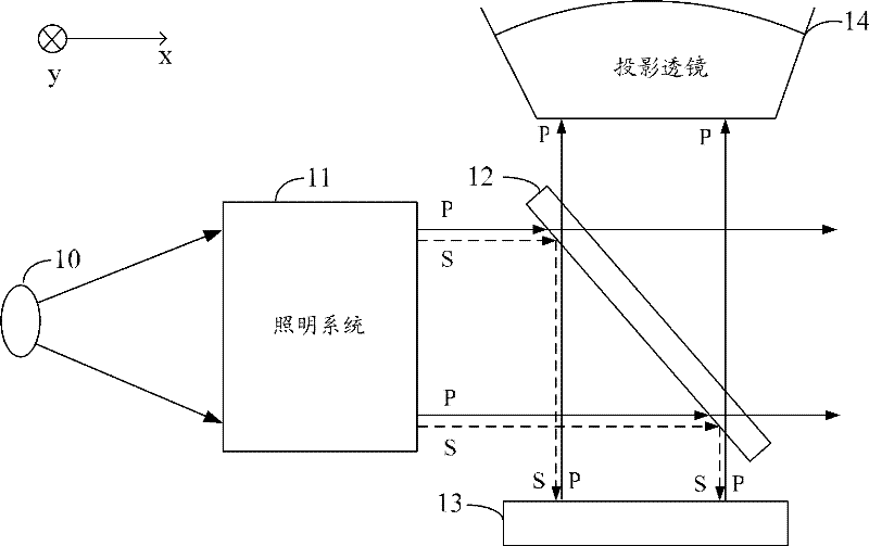
[0033] In the projection display device of the prior art, after the natural light generated by the natural light source is converted into P polarized light and S polarized light by the lighting system, one of them is reflected by the polarizing beam splitter and then enters the display substrate, and is finally reflected to the projection lens. The transmitted polarized light is wasted, so that the light intensity utilization rate of the entire projection display device is low, and the imaging effect is poor.

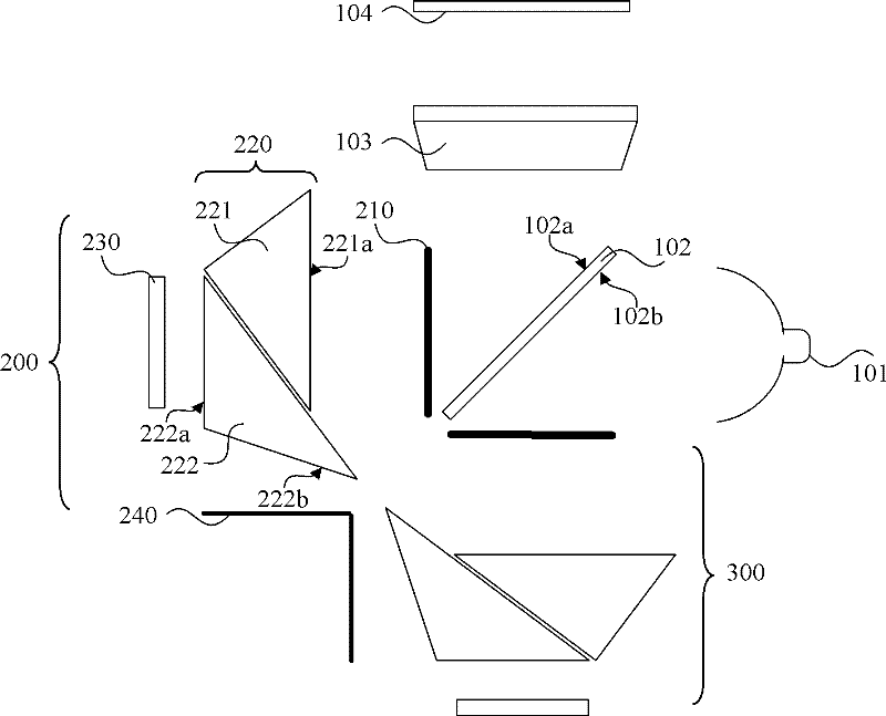
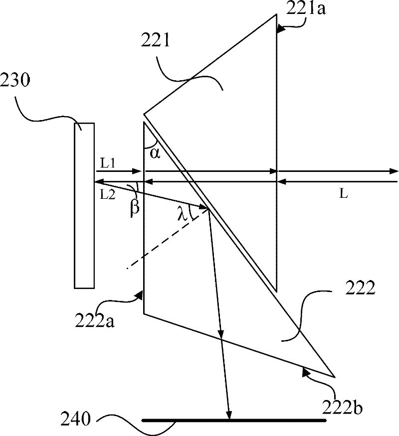
[0034]In order to solve the above-mentioned problems in the prior art, the inventors of the present invention have designed a stereoscopic projection system, which splits, transforms, recombines and pr...


PUM


Abstract

The invention provides a stereo-projection system. The stereo-projection system comprises a stereo light source, a polarization beam splitter, a projection lens, a first display mirror group and a second display mirror group, wherein the first display mirror group is used for converting a first polarization light which carries first image information and is emitted from a second surface of the polarization beam splitter into a second polarization light which carries the first image information, and reflecting the second polarization light to the second surface; the second display mirror groupis used for converting the second polarization light which carries second image information and is emitted from a first surface of the polarization beam splitter into the first polarization light which carries the second image information, and reflecting the first polarization light to the first surface; and through conversion of the display mirror groups, the second polarization light which carries the first image information and is emitted from the second surface of the polarization beam splitter and the first polarization light which carries the second image information are projected on anexternal receiving screen by the projection lens. The stereo-projection system has relatively high light source utilization ratio and a better image restoration effect.

Description

technical field [0001] The invention relates to the technical field of optical instruments, in particular to a stereoscopic projection system. Background technique [0002] Projection systems are used to magnify and project images, and are widely used in people's daily life, such as projection systems built into digital cameras, handheld projectors, and the like. With its application becoming more and more extensive, the technology related to the projection system has also been greatly developed. [0003] With the development of projection technology, stereoscopic projection systems have also begun to be applied. Different from conventional 2D images, stereoscopic images are not composed of RGB three primary colors. For example, 3D polarization is a common stereoscopic image display method, and the natural light generated by its light source includes P-polarized light and S-polarized light. [0004] figure 1 A schematic structural view of a stereoscopic projection display...

Claims


Application Information

Patent Timeline
Patent Type & Authority Patents(China)
IPC IPC(8): G02B27/26G02B17/08G02B27/18G02B27/28G02B27/10G02B5/30G03B21/14G02B30/25
Inventor 黄城张镭
Owner XIAN ZHONGKE JINGXIANG PHOTOELECTRIC SCI & TECH
Why Eureka
Try Eureka