
Repairing circuit for displaying panel

A display panel and liquid crystal display panel technology, applied in static indicators, nonlinear optics, instruments, etc., can solve problems such as increased defect rate, and achieve the effect of avoiding insufficient charging and reducing panel scrap rate

Inactive Publication Date: 2011-08-17
AU OPTRONICS CORP
View PDF0 Cites 6 Cited by
  • Summary
  • Abstract
  • Description
  • Claims
  • Application Information

AI Technical Summary

Problems solved by technology

[0005] As the GOA technology is applied to the small board (slim boarder) LCD, in order to reduce the space occupied by the display panel, the distance between the GOA bus (Bus line) and the glass cutting edge is getting shorter and shorter. The defect rate caused by damage to the GOA bus also increases

Method used


Image

  • Repairing circuit for displaying panel
  • Repairing circuit for displaying panel
  • Repairing circuit for displaying panel

Examples


Embodiment Construction

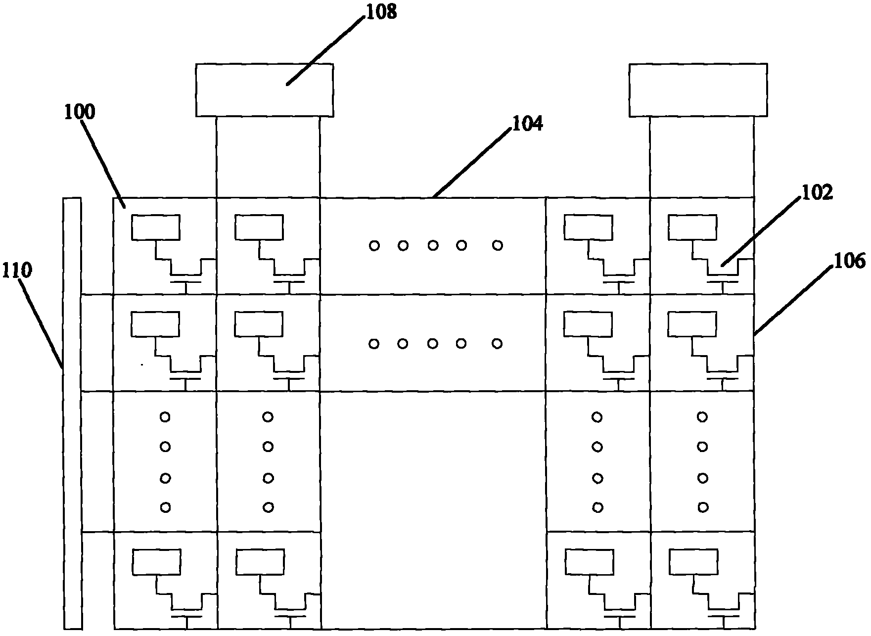
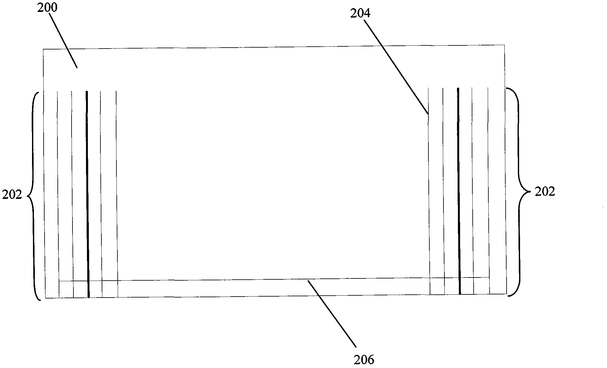
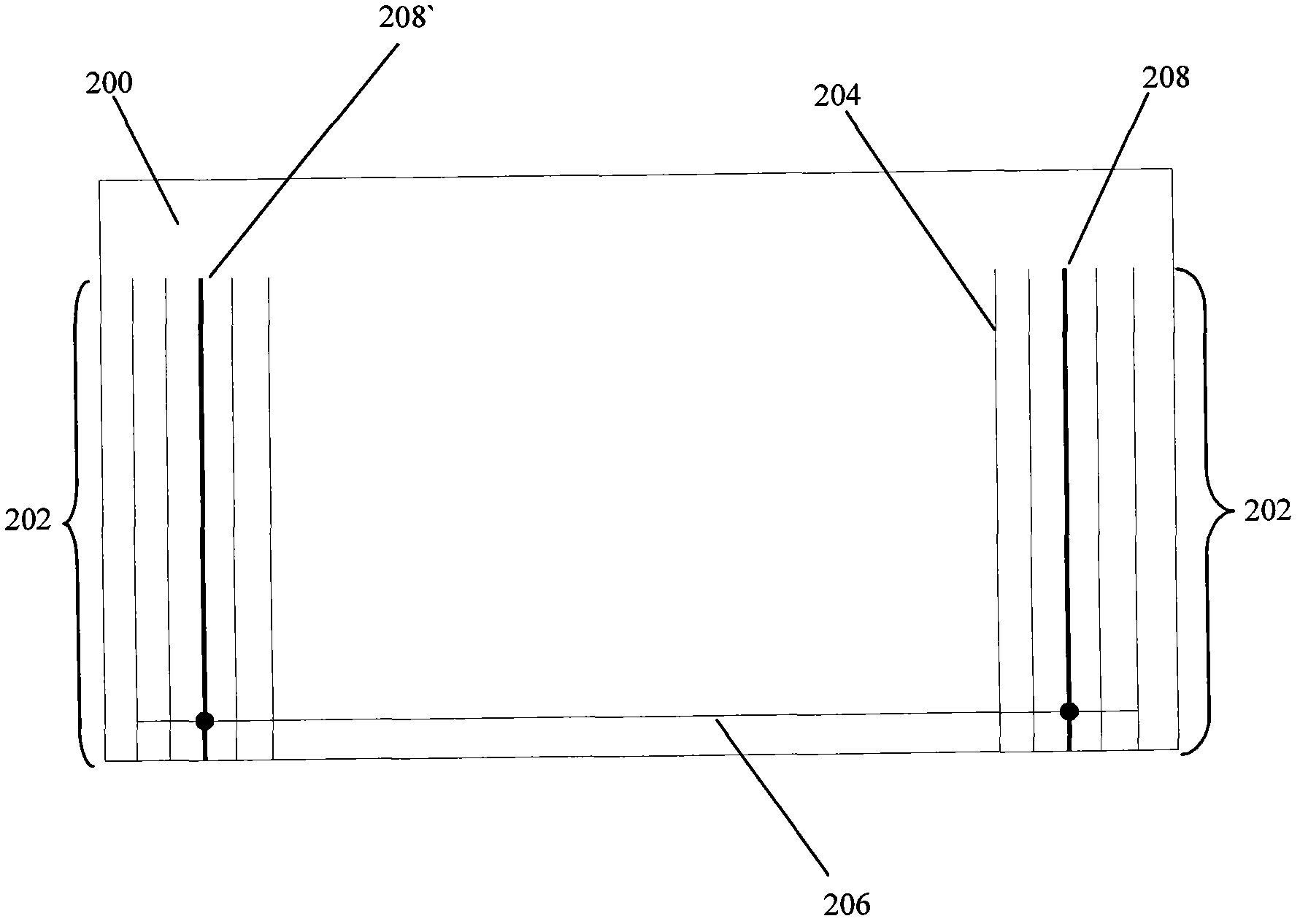
[0017] The specific implementation manners of the present invention will be described in further detail below with reference to the accompanying drawings. Throughout the description, like reference numerals refer to like parts. It should be understood that in the drawings of this application, the "solid lines" and "dotted lines" used to electrically connect a certain component with another component are only for the convenience of describing specific embodiments of the present invention, and are not intended to induce It will be understood by those skilled in the art that solid lines indicate electrical connection and dashed lines indicate electrical isolation. Any person skilled in the art, after understanding the preferred embodiments of the present invention, can make changes and modifications based on the technology disclosed in the present invention without departing from the spirit and scope of the present invention.

[0018] refer to figure 1 , which is a schematic ci...


PUM


Abstract

The invention provides a repairing circuit for a displaying panel, comprising a substrate, two groups of bus-bars, and at least one repairing wire, wherein the two groups of bus-bars are arranged on the substrate; each group of bus-bar comprises a plurality of identical leads; the at least one repairing wire is arranged above or below the bus-bar in an insulating manner and is crossed to each lead. The repairing circuit can introduce the signal of the lead at the other side when the lead of one bus-bar of the displaying panel driven at two sides is cracked, thus repairing the dual-sided driving function and avoiding the insufficiently charging problem resulting from single-sided driving; furthermore, the reject rate of the panel due to fracture of the lead can be reduced; and the space occupied by the repairing wire is not enlarged, and the identical panel design is maintained.

Description

technical field [0001] The present invention relates to a display panel repair circuit, in particular to a display panel repair circuit using array substrate row driving technology. Background technique [0002] In an active matrix liquid crystal display (Active Matrix Liquid Crystal Display), each pixel has a TFT, its gate (Gate) is connected to the horizontal direction scanning line, the drain (Drain) is connected to the vertical direction data line, and the source Level (Source) is connected to the pixel electrode. [0003] If enough positive voltage is applied to a scanning line in the horizontal direction, all the TFTs on the line will be turned on. At this time, the pixel electrodes on the line will be connected to the data lines in the vertical direction, and the data lines on the data lines will be connected to each other. The video signal voltage is written into the pixel to control the transmittance of different liquid crystals to achieve the effect of color contr...

Claims


Application Information

Patent Timeline
Patent Type & Authority Applications(China)
IPC IPC(8): G02F1/1362G02F1/133G02F1/13
Inventor 林政豪吴威宪
Owner AU OPTRONICS CORP
Learn More