
Pipeline crack equivalent stiffness calculation method based on stress intensity factor

A technology of stress intensity factor and equivalent stiffness, applied in the field of effective stiffness calculation, can solve the problems that are not conducive to revealing the law of crack equivalent stiffness change, tedious experimental work, etc.

Active Publication Date: 2011-08-17
盐城韩资工业园产业发展有限公司
View PDF0 Cites 11 Cited by
  • Summary
  • Abstract
  • Description
  • Claims
  • Application Information

AI Technical Summary

Problems solved by technology

The equivalent stiffness of the crack can be obtained by using the experimental method, but it requires a lot of tedious experimental work, and it is impossible to conduct experiments on cracks at all positions
At the same time, the experimental method is not conducive to revealing the law of the change of crack equivalent stiffness.

Method used


Image

  • Pipeline crack equivalent stiffness calculation method based on stress intensity factor
  • Pipeline crack equivalent stiffness calculation method based on stress intensity factor
  • Pipeline crack equivalent stiffness calculation method based on stress intensity factor

Examples


Embodiment 1

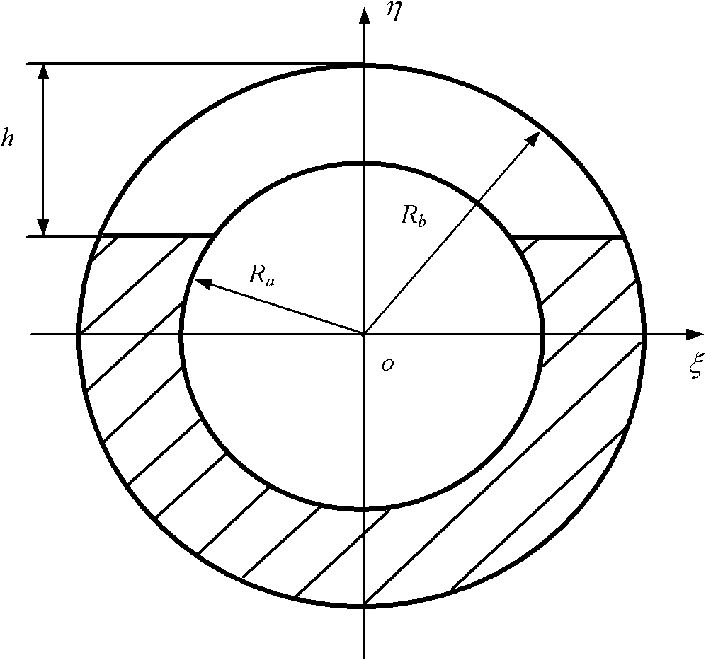
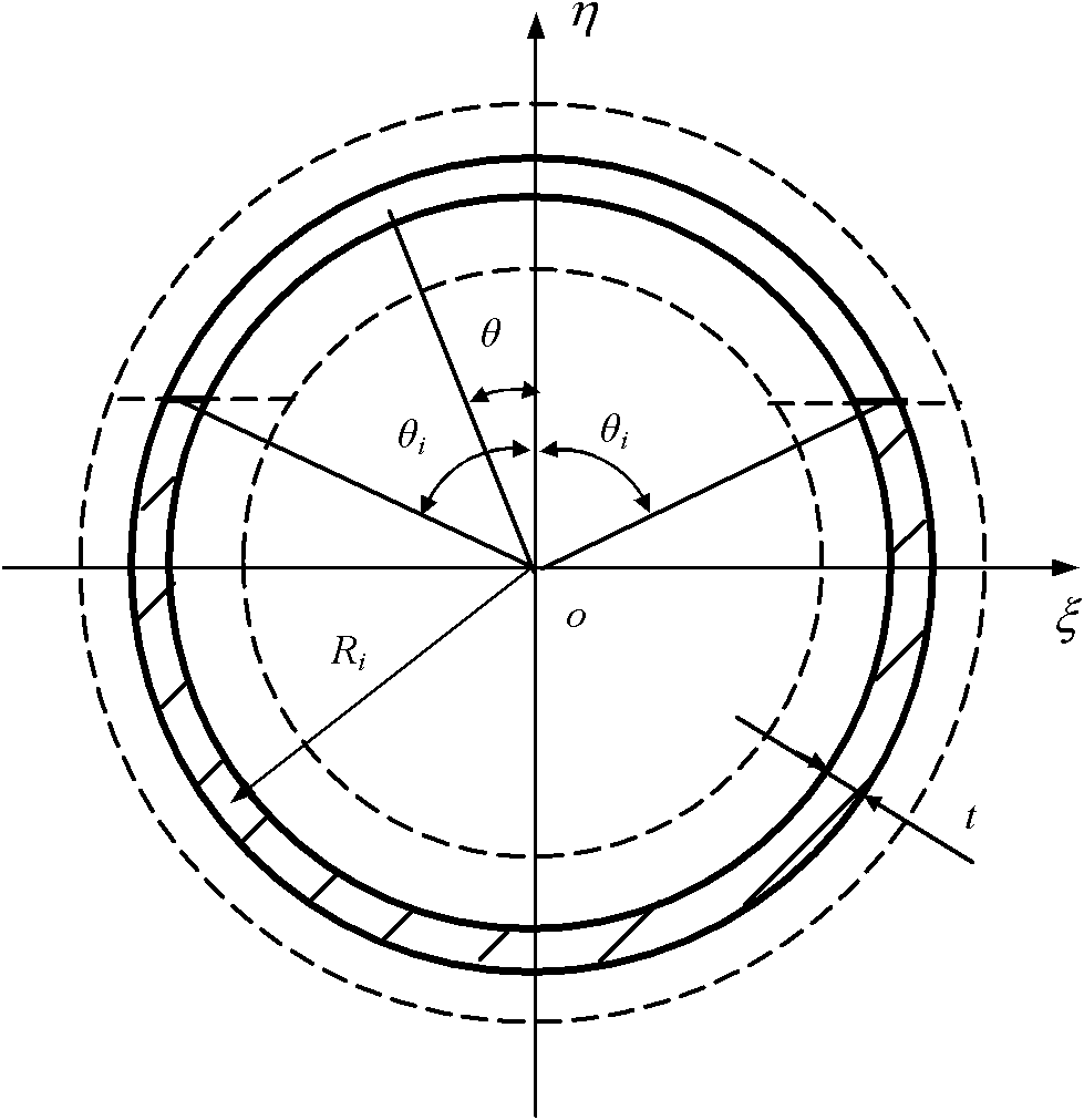
[0093] This embodiment mainly verifies the convergence of the method for calculating the equivalent stiffness of pipeline cracks disclosed in the present invention. The cracked pipe is divided into n thin-walled rings, and the parameters of the pipe are as follows: R b =0.0189m, v=0.3, E=173.81GPa, R a =0.0139m, ρ=7860kg / m 3 .

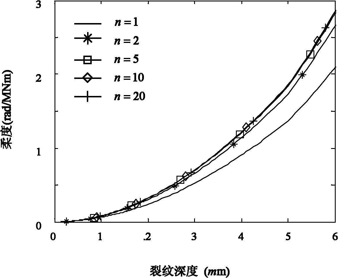
[0094] Since the equivalent stiffness of the crack is large when the crack depth is relatively small (when the crack depth is 0, the equivalent stiffness is infinite), and then decays rapidly, it is not intuitive to use the stiffness diagram for research. Since flexibility and stiffness are reciprocals of each other, the flexibility diagram of the crack is used for research here. The pipe is discretized into n thin-walled rings along the radial direction, and the values ​​of n are taken as 1, 2, 5, 10, and 20, respectively. As n increases, the calculated value of crack equivalent stiffness converges to the exact solution, as image 3 shown. The a...

Embodiment 2

[0096] This embodiment mainly verifies the effectiveness of the method for calculating the equivalent stiffness of pipeline cracks disclosed in the present invention in diagnosing pipeline cracks. The cracked pipe is divided into n thin-walled rings, and the parameters of the pipe are as follows: R b =0.0189m, v=0.3, E=173.81GPa, R a =0.0139m, ρ=7860kg / m 3 .

[0097] The appearance of cracks can cause changes in the local stiffness of the structure, resulting in changes in the natural frequency of the system. Structural cracks can be diagnosed by looking for the relationship between the natural frequency and the position and size of the crack. In this embodiment, the method disclosed in the present invention is used to calculate the equivalent stiffness of pipeline cracks at different positions and sizes, and then obtain the change law of the first three natural frequencies of the system relative to the position and size of cracks. Then draw the contour lines of the first ...


PUM


Abstract

The invention discloses a pipeline crack equivalent stiffness calculation method based on a stress intensity factor. In the method, pipeline structures are scattered into a series of sequentially nested thin-wall rings along the radial direction so that the stress intensity factors of the pipeline structures are solved, and then the equivalent stiffness of cracks is calculated. In the research ofa vibration-based crack diagnosis method, the structural local stiffness change caused by the cracks can be described by adopting a torsion line spring model. Therefore, the acquired equivalent stiffness of the cracks can be used for identifying the position and the size of the cracks of a pipeline. By the method, the equivalent stiffness of the crack at any position in the pipeline can be acquired, a large amount of fussy experiment work is avoided, the result is reliable, the operation is simple and feasible, and a foundation is provided for further diagnosing the cracks of the pipeline.

Description

technical field [0001] The invention belongs to the field of fault diagnosis of mechanical equipment, and in particular relates to a method for calculating equivalent stiffness of pipeline cracks based on stress intensity factors. Background technique [0002] Pipeline is one of the five major means of transportation including railway, highway, water transportation and air transportation, and occupies an extremely important position in petrochemical and other production. With the continuous occurrence of pipeline accidents, the damage detection of the safety performance of pipelines has become a hot topic at present. At present, the non-destructive testing technologies used in pipeline systems mainly include magnetic flux leakage testing technology, ultrasonic testing technology, eddy current testing technology, acoustic emission technology and vibration testing. Vibration detection obtains vibration parameters through dynamic measurement of pipeline structure, and takes th...

Claims


Application Information

Patent Timeline
Patent Type & Authority Applications(China)
IPC IPC(8): G06F19/00
Inventor 何育民张小龙林云
Owner 盐城韩资工业园产业发展有限公司
Learn More