
Systems and Methods for Performing Stress Intensity Factor Calculations Using Non-Singluar Finite Elements

a stress intensity factor and non-singluar finite element technology, applied in the field of fracture mechanics, can solve the problems that the parameters needed for fracture mechanics calculations such as the stress intensity factor or the j integral cannot be extracted, and restrict the application of fracture mechanics by the wider engineering community

Active Publication Date: 2011-08-04
KELLOGG BROWN & ROOT LLC
View PDF11 Cites 13 Cited by
  • Summary
  • Abstract
  • Description
  • Claims
  • Application Information

AI Technical Summary

Problems solved by technology

There is a fundamental problem though when it comes to modeling cracks, because the gradient of the stress / stain field is large and approaches infinity at the crack tip.
Moreover, the parameters needed for fracture mechanics calculations such as the stress intensity factor or the J integral can only be extracted from finite element results with specialized post processing algorithms.
Such analyses remain the province of the specialist, therefore, restricting the application of fracture mechanics by the wider engineering community.

Method used


Image

  • Systems and Methods for Performing Stress Intensity Factor Calculations Using Non-Singluar Finite Elements
  • Systems and Methods for Performing Stress Intensity Factor Calculations Using Non-Singluar Finite Elements
  • Systems and Methods for Performing Stress Intensity Factor Calculations Using Non-Singluar Finite Elements

Examples


Embodiment Construction

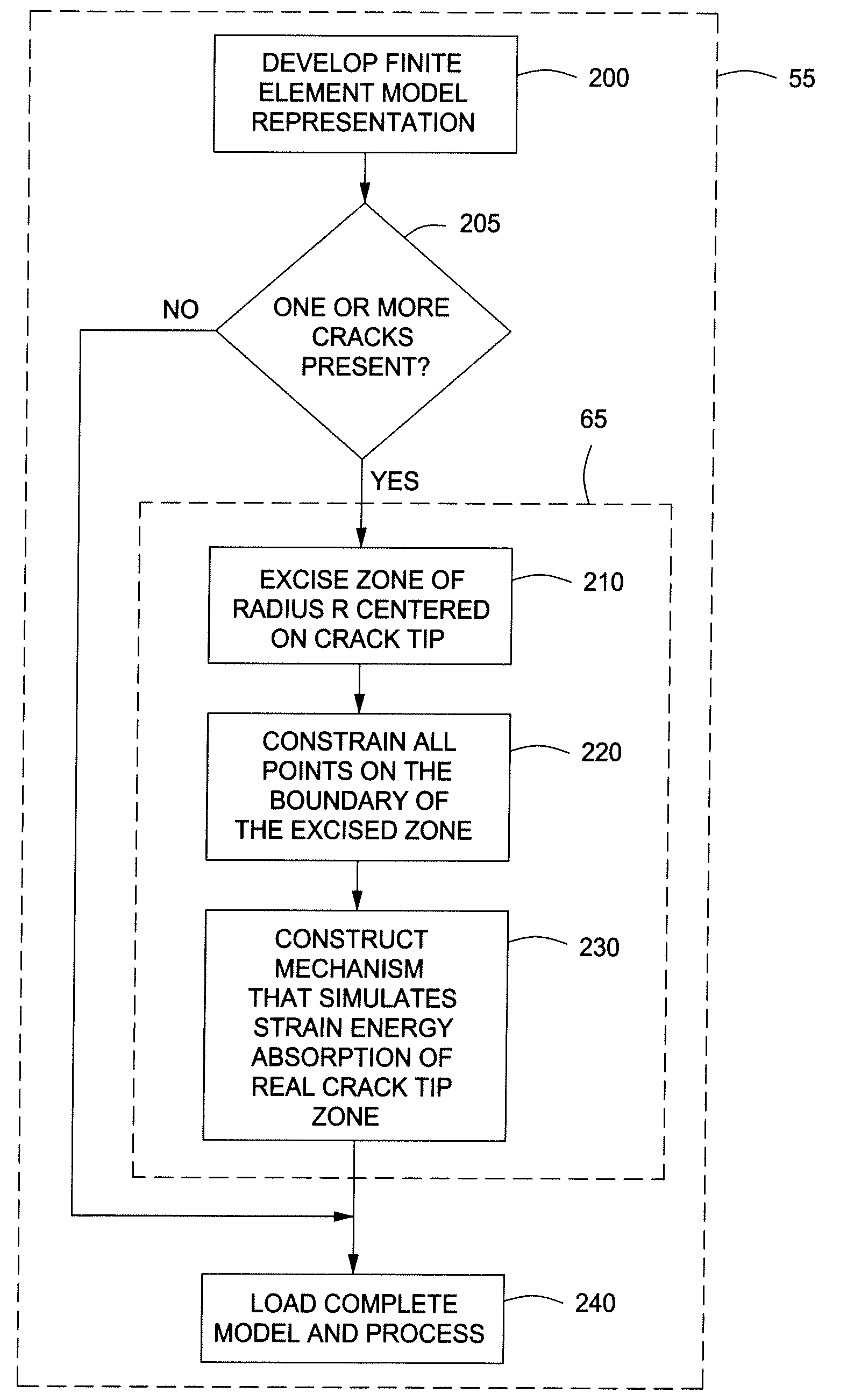
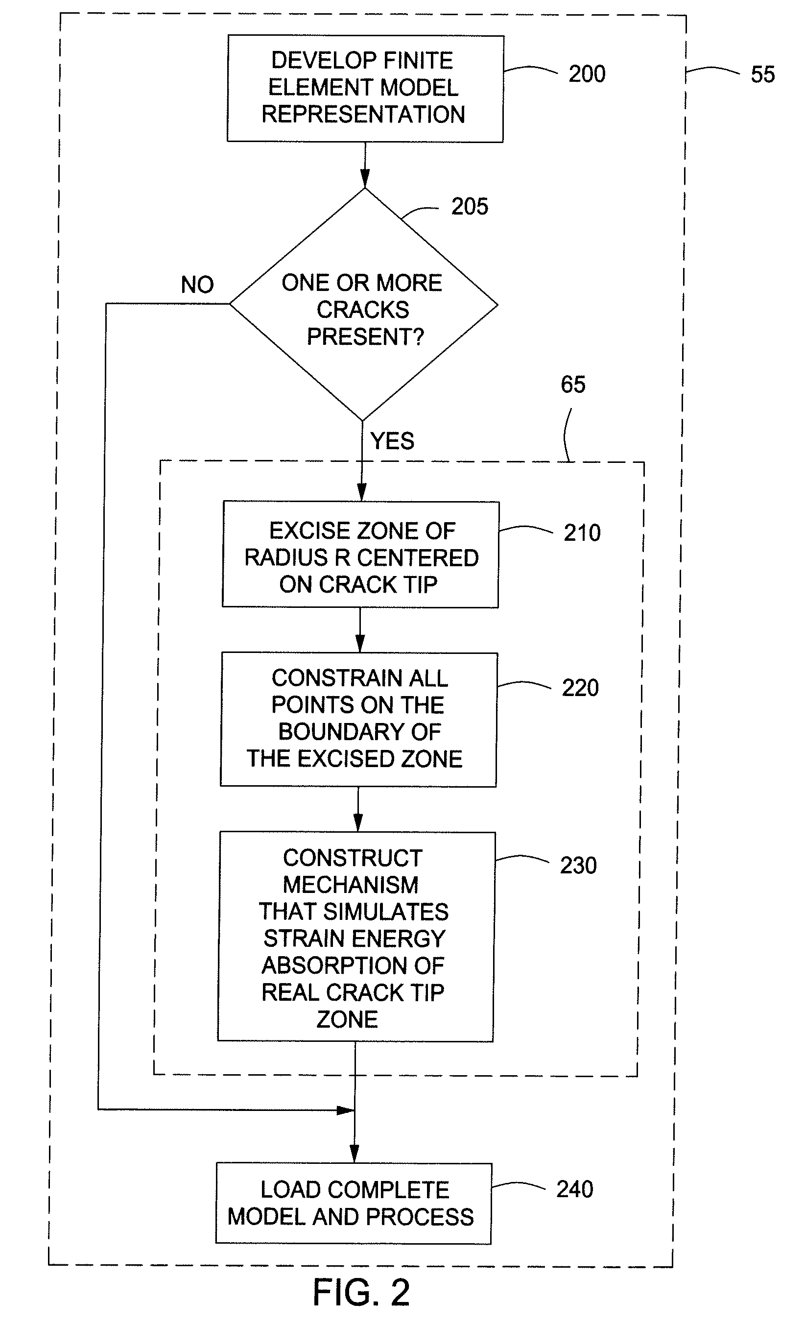
[0017]Systems and methods are disclosed for determining stress intensity factors. In one or more embodiments, the method can include the steps of defining a crack tip zone about one or more crack tips of one or more arbitrarily shaped cracks in an arbitrarily shaped solid. The one or more crack tip zones can be constrained within a finite element model representation mesh of the arbitrarily shaped solid to provide one or more constrained crack tip zones. The combination of the finite element model representation mesh and the one or more constrained crack tip zones can be processed to determine the stress intensity factor for each of the one or more arbitrarily shaped cracks.

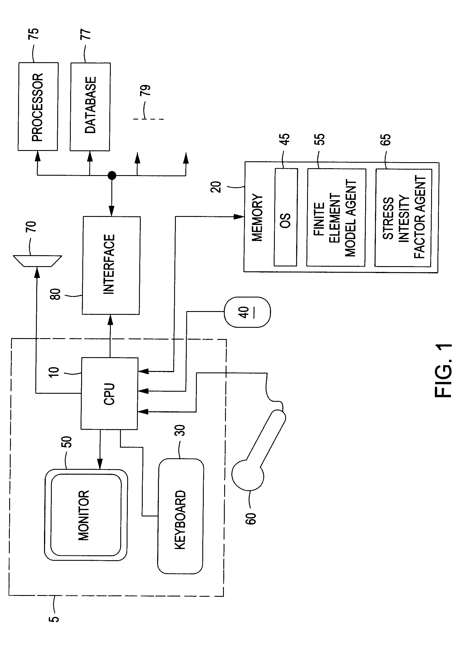
[0018]FIG. 1 depicts a representative system 100 for performing crack analyses using stress intensity factor calculations from non-singular finite elements, according to one or more embodiments described. The system 100 can include a computer 5 can include a central processing unit 10, an input device or keyboard...


PUM


Abstract

Systems and methods are disclosed for determining stress intensity factors. In one or more embodiments, the method can include the steps of defining a crack tip zone about one or more crack tips of one or more arbitrarily shaped cracks in an arbitrarily shaped solid. The one or more crack tip zones can be constrained within a finite element model representation mesh of the arbitrarily shaped solid to provide one or more constrained crack tip zones. The combination of the finite element model representation mesh and the one or more constrained crack tip zones can be processed to determine the stress intensity factor for each of the one or more arbitrarily shaped cracks.

Description

CROSS-REFERENCE TO RELATED APPLICATIONS[0001]This application claims the benefit of U.S. Provisional Patent Application having Ser. No. 61 / 301,022, filed on Feb. 3, 2010, which is incorporated by reference herein.BACKGROUND[0002]1. Field[0003]Embodiments described herein generally relate to fracture mechanics. More particularly, embodiments described herein relate to performing crack analyses using stress intensity factor calculations from non-singular finite elements.[0004]2. Description of the Related Art[0005]Fracture mechanics is an immensely powerful tool that allows rational predictions to be made with regard to the ultimate strength and residual fatigue life of cracked structures. Finite element techniques exist that are appropriate for the analysis of cracks, but they generally rely on the use of specialized crack tip elements. There is a fundamental problem though when it comes to modeling cracks, because the gradient of the stress / stain field is large and approaches infini...

Claims


Application Information

Patent Timeline
Patent Type & Authority Applications(United States)
IPC IPC(8): G06F17/10
CPCG06F17/10G06F30/23G01N2203/0066G01N2203/0212G06F2119/04
Inventor HOLDBROOK, STEPHEN J.
Owner KELLOGG BROWN & ROOT LLC
Learn More