Linear permanent magnet motor operating mechanism of high-voltage circuit breaker

A high-voltage circuit breaker and operating mechanism technology, which is applied to the field of linear permanent magnet motor operating mechanisms, can solve the problems of difficulty in meeting the long-stroke opening and closing operation requirements of the high-voltage circuit breaker, the short stroke of the permanent magnet mechanism, and the difficulty in guaranteeing the opening and closing operation. , to reduce the risk of irreversible demagnetization, increase the magnetic field density, and increase the torque density

Inactive Publication Date: 2011-08-17
SOUTHEAST UNIV
View PDF7 Cites 3 Cited by
  • Summary
  • Abstract
  • Description
  • Claims
  • Application Information

AI Technical Summary

Problems solved by technology

[0005]Technical problem: the invention aims at the short stroke of traditional electromagnetic, spring and permanent magnet mechanisms, which is difficult to meet the long-stroke opening and closing operation requirements of high-voltage circuit breakers. To solve the problem that the closing operation is difficult to guarantee, a long-stroke linear permanent magnet motor operating mechanism is provided to meet the opening and closing operation requirements of long-stroke high-voltage circuit breakers under the condition of outputting a certain electromagnetic operating force

Method used


Image

  • Linear permanent magnet motor operating mechanism of high-voltage circuit breaker
  • Linear permanent magnet motor operating mechanism of high-voltage circuit breaker
  • Linear permanent magnet motor operating mechanism of high-voltage circuit breaker

Examples


Embodiment Construction

[0020] The present invention will be further described below in conjunction with accompanying drawing.

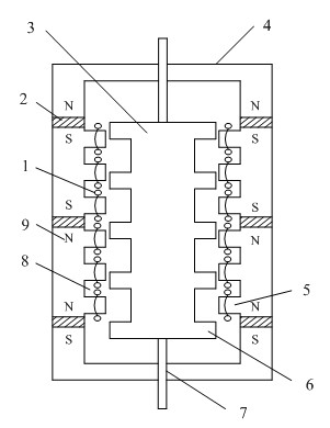
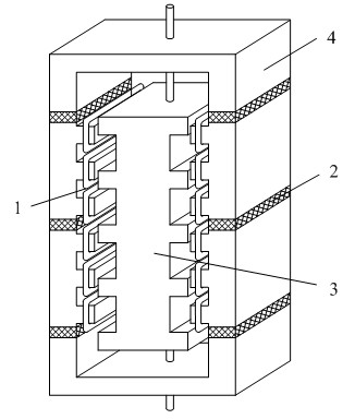
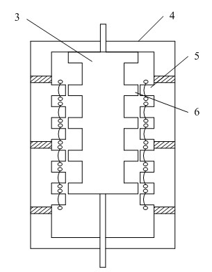
[0021] Depend on figure 1 It can be seen that a linear permanent magnet motor operating mechanism for a high-voltage circuit breaker includes a stator core 4, a mover core 3, a drive rod 7, and a permanent magnet 2. The stator core 4 is a box, and the mover core 3 is placed In the stator core 4, the drive rods 7 arranged at both ends of the mover core 3 pass through the shells at both ends of the stator core 4 and can move up and down. The side walls of the stator core 4 are provided with permanent magnets 2, and the poles of the upper and lower adjacent permanent magnets opposite, that is, the polarities of the opposite faces of the upper and lower adjacent permanent magnets are the same, such as figure 1 As shown in , the N poles to N poles, S poles to S poles of the adjacent permanent magnets up and down, and the permanent magnets on the left and right sides of the bo...


PUM


Abstract

The invention relates to a linear permanent magnet motor operating mechanism of a high-voltage circuit breaker, comprising a stator core, a rotor core, drive rods and permanent magnets, wherein the stator core is a box body; the rotor core is arranged in the stator core; the drive rods arranged on both ends of the rotor core penetrate through shells positioned on the upper and the lower ends of the rotor core and can move up and down; the side wall of the stator core is provided with the permanent magnets; upper and lower adjacent permanent magnets are opposite in polarity; the permanent magnets positioned on the left and the right edges of the box body are same in polarity placement directions; stator salient poles with the number of integral multiples of a phase number are arranged on the inner side wall of the stator core and between the two adjacent permanents and are provided with armature coils; the outer side wall of the rotor core is provided with rotor salient poles; when therotor core is positioned on a highest position, the stator salient pole positioned on the uppermost end of the stator core just faces to the rotor salient poles; and when the rotor core is positionedon a lowest position, the stator salient pole positioned on the lowest end of the stator core just faces to the rotor salient poles.

Description

technical field [0001] The invention belongs to the technical field of switchgear in electrical engineering, and in particular relates to a linear permanent magnet motor operating mechanism of a high-voltage circuit breaker. Background technique [0002] The operating mechanisms of traditional high-voltage circuit breakers mainly include hydraulic mechanisms, pneumatic mechanisms, spring mechanisms and electromagnetic mechanisms. The hydraulic operating mechanism has a series of advantages such as high energy intensity, fast response, low noise, and reliable action. The pneumatic operating mechanism uses compressed air as an energy source to generate thrust, and does not require high-power DC power supply or laying control cables. Pneumatic and hydraulic systems can meet the long-stroke and high-power operation requirements, and are mainly used in high-voltage circuit breakers with high voltage levels. However, the system is complex and the reliability is not high enough. Th...

Claims


Application Information

Patent Timeline
Patent Type & Authority Applications(China)
IPC IPC(8): H01H71/10H01H3/26
Inventor 张建忠程明王敏希
Owner SOUTHEAST UNIV
Why Eureka
Try Eureka