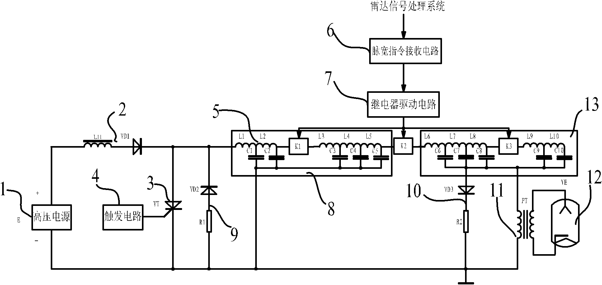
Pulse width switching circuit structure

A conversion circuit and pulse width technology, which is applied in the field of radar transmitter pulse modulation, can solve the problems of not being able to meet the needs of Doppler weather radar weather detection business and research, affecting the application of weather radar, and the high cost of Doppler weather radar. Achieve the effects of simple structure, wide application range, and reduced transformation costs

Active Publication Date: 2011-08-17
北方通用电子集团有限公司
View PDF9 Cites 7 Cited by
  • Summary
  • Abstract
  • Description
  • Claims
  • Application Information

AI Technical Summary

Problems solved by technology

[0003] At present, digital weather radars occupy a large share in the market. The digital weather radars cannot adapt to the weather detection business and research needs of Doppler weather radars, which affects the application of weather radars; the high cost of Doppler weather radars will The modification of digital weather radar to enable it to have the function of Doppler weather radar requires adjusting the structure of the linear pulse modulator to meet the requirements of Doppler weather radar

Method used


Image

  • Pulse width switching circuit structure
  • Pulse width switching circuit structure
  • Pulse width switching circuit structure

Examples


Embodiment Construction

[0019] The present invention will be further described below in conjunction with specific drawings and embodiments.

[0020] Such as figure 1 Shown: the present invention includes a high-voltage power supply 1, a charging isolation circuit 2, a discharge switch 3, a trigger circuit 4, a Blumlein pulse forming network 5, a pulse width command receiving circuit 6, a relay driving circuit 7, a first pulse forming network 8, and an inverse peak Circuit 9, damping circuit 10, pulse transformer 11, microwave tube 12, second pulse forming network 13, first high voltage relay K1, second high voltage relay K2, and third high voltage relay K3.

[0021] Such as figure 1 As shown: Blumlein pulse forming network 5 includes several pulse forming network capacitors and pulse forming network inductors matched with the pulse forming network capacitors. The number of pulse forming network inductors matches the number of pulse forming network capacitors to form a transmission line. The time delay cau...


PUM


Abstract

The invention relates to a pulse width switching circuit structure, comprising a Blumlein pulse forming network (PFN), wherein the Blumlein PFN is provided with a second high-voltage relay K2 which is used for dividing the Blumlein PFN into a first PFN and a second PFN; the first PFN and the second PFN are distributed uniformly and symmetrically; the first PFN is internally provided with at leastone first high-voltage relay K1; the second PFN is internally provided with at least one third high-voltage relay K3; the third high-voltage relay K3 is arranged corresponding to the first high-voltage relay K1, thus a pulse network structure which is divided by the third high-voltage relay K3 in the second PFN corresponds to a pulse network structure which is divided by a first relay in the first PFN; and coils of the first high-voltage relay K1, the second high-voltage relay K2 and the third high-voltage relay K3 are connected with a relay drive circuit. The pulse width switching circuit structure is convenient to install and use and wide in applicable scope, reduces the reformation cost of digital weather radars, and is safe and reliable.

Description

Technical field [0001] The invention relates to a circuit structure, in particular to a pulse width conversion circuit structure, in particular to a circuit structure for pulse width conversion of Blumlein pulse forming network in a radar vacuum microwave tube transmitter linear pulse modulator, belonging to radar transmitter The technical field of machine pulse modulation. Background technique [0002] The linear pulse modulator is an important part of the current high-power vacuum microwave tube transmitter, and it is also a commonly used modulation scheme; it is mainly used for the microwave source of radar transmitters that work in pulse mode. The pulse width of the linear pulse modulator is determined by the pulse forming network. Its theoretical basis is the transmission line. The pulse width is formed by the time delay caused by the transmission of the wave in the transmission line. In actual use, the capacitance, The inductance forms a chain structure network instead of ...

Claims


Application Information

Patent Timeline
Patent Type & Authority Applications(China)
IPC IPC(8): H02M3/07G01S7/28G01S7/282
Inventor 孙导徐石龙韩寅冬刘胜路风
Owner 北方通用电子集团有限公司
Why Eureka
Try Eureka