Semi-continuous high-speed spinning machine
A semi-continuous, spinning machine technology, applied in textiles and papermaking, clustering of newly extruded filaments, cleaning/drying of artificial filaments, etc., can solve problems such as inability to increase spinning speed and insufficient response of filaments
- Summary
- Abstract
- Description
- Claims
- Application Information
AI Technical Summary
Problems solved by technology
Method used
Image
Examples
Embodiment 1
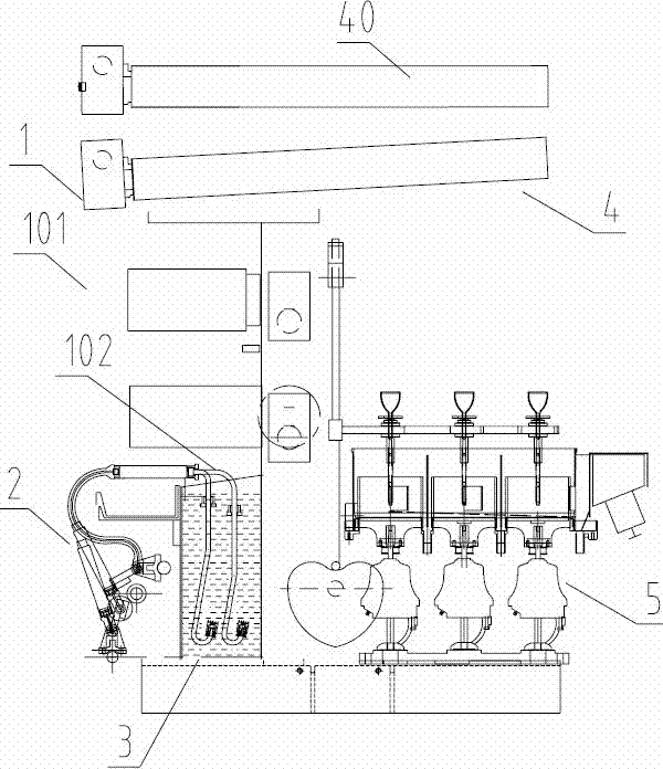
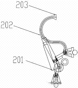
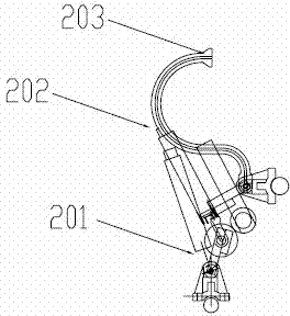
[0307] The semi-continuous high-speed spinning machine comprises a frame 1, a glue supply device 2, a filament forming device 3, a spinning device 4 and a winding device 5, and the operation of the spinning roller 40 relative to the spinning surface 101 in the spinning device 4 The surface 102 is arranged transversely, and the filament 8 is wound on the spinning roll 40 . The operating surface 102 of the spinning surface 101 is a horizontal working surface located in the spinning surface area; the horizontal setting with respect to the operating surface 102 of the spinning surface 101 means that when the spinning worker faces the winding device 5, the spinning The rolls 40 are mounted transversely with respect to the spinner.
[0308] The transmission structure of the semi-continuous spinning machine after the spinning rolls 40 are arranged horizontally is simplified, and the number of traditional multiple spinning rolls 40 is reduced to at least one, thereby simplifying the t...
Embodiment 2
[0310] The semi-continuous high-speed spinning machine comprises a frame 1, a glue supply device 2, a filament forming device 3, a spinning device 4 and a winding device 5, and the operation of the spinning roller 40 relative to the spinning surface 101 in the spinning device 4 The surface 102 is arranged transversely, and the filament 8 is wound on the spinning roll 40 . The operating surface 102 of the spinning surface 101 is a horizontal working surface located in the spinning surface area; the horizontal setting with respect to the operating surface 102 of the spinning surface 101 means that when the spinning worker faces the winding device 5, the spinning The rolls 40 are mounted transversely with respect to the spinner. Spinning rolls 40 include rolls that perform the functions of drafting, coagulation, and / or deacidification. The two ends of each spinning roller 40 are respectively fixed above the two sides of the frame 1 and connected to the driving device for rotatio...
Embodiment 3
[0313] Such as Figure 7 , Figure 8 and Figure 15 As shown, the single-roll semi-continuous high-speed spinning machine provided by the present embodiment includes a frame 1, a glue supply device 2, a filament forming device 3, a spinning device 4, and a winding device 5, and the spinning device 4 includes a spinning device. The spinning roll 40 and the spinning roll 40 are arranged transversely to the spinning surface operation surface.
[0314] Such as Figure 9 As shown, the operating surface of the spinning surface is a horizontal working surface located in the spinning surface area, and the horizontal arrangement of the spinning roller 40 relative to the operating surface of the spinning surface means that when the spinning worker faces the winding device, the spinning roller 40 is installed horizontally relative to spinning workers.
[0315] The two ends of the spinning roller 40 are respectively fixed above the two sides of the frame, and are connected with a driv...
PUM
| Property | Measurement | Unit |
|---|---|---|
| Taper | aaaaa | aaaaa |
| Taper | aaaaa | aaaaa |
| Taper | aaaaa | aaaaa |
Abstract
Description
Claims
Application Information
 - R&D
- Intellectual Property
- Life Sciences
- Materials
- Tech Scout
- Unparalleled Data Quality
- Higher Quality Content
- 60% Fewer Hallucinations
Browse by: Latest US Patents, China's latest patents, Technical Efficacy Thesaurus, Application Domain, Technology Topic, Popular Technical Reports.
© 2025 PatSnap. All rights reserved.Legal|Privacy policy|Modern Slavery Act Transparency Statement|Sitemap|About US| Contact US: help@patsnap.com


