
Video monitoring system and method

A video surveillance system and moving target technology, applied in the field of image processing, can solve the problems of poor user experience, dropped frames, slow wireless network transmission rate, etc., to achieve the effect of improving efficiency and reducing the demand for wireless network bandwidth

Active Publication Date: 2011-08-17
NANJING ZGMICRO CO LTD
View PDF6 Cites 38 Cited by
  • Summary
  • Abstract
  • Description
  • Claims
  • Application Information

AI Technical Summary

Problems solved by technology

However, the wireless network transmission rate supported by mobile devices is usually slow, and the large-resolution surveillance images collected by surveillance cameras cannot be transmitted smoothly. see details
Therefore, when the user uses the mobile device to display after receiving the alarm, the picture will often be stuck and the frame will be dropped, and the details of the moving target cannot be seen clearly. The user experience is very poor.

Method used


Image

  • Video monitoring system and method
  • Video monitoring system and method
  • Video monitoring system and method

Examples


Embodiment Construction

[0027] The detailed description of the present invention directly or indirectly simulates the operation of the technical solution of the present invention mainly through programs, steps, logic blocks, processes or other symbolic descriptions. In the ensuing description, numerous specific details are set forth in order to provide a thorough understanding of the present invention. Rather, the invention may be practiced without these specific details. These descriptions and representations herein are used by those skilled in the art to effectively convey the substance of their work to others skilled in the art. In other words, for the purpose of avoiding obscuring the present invention, well-known methods, procedures, components and circuits have not been described in detail since they are readily understood.

[0028] Reference herein to "one embodiment" or "an embodiment" refers to a particular feature, structure or characteristic that can be included in at least one implementa...


PUM


Abstract

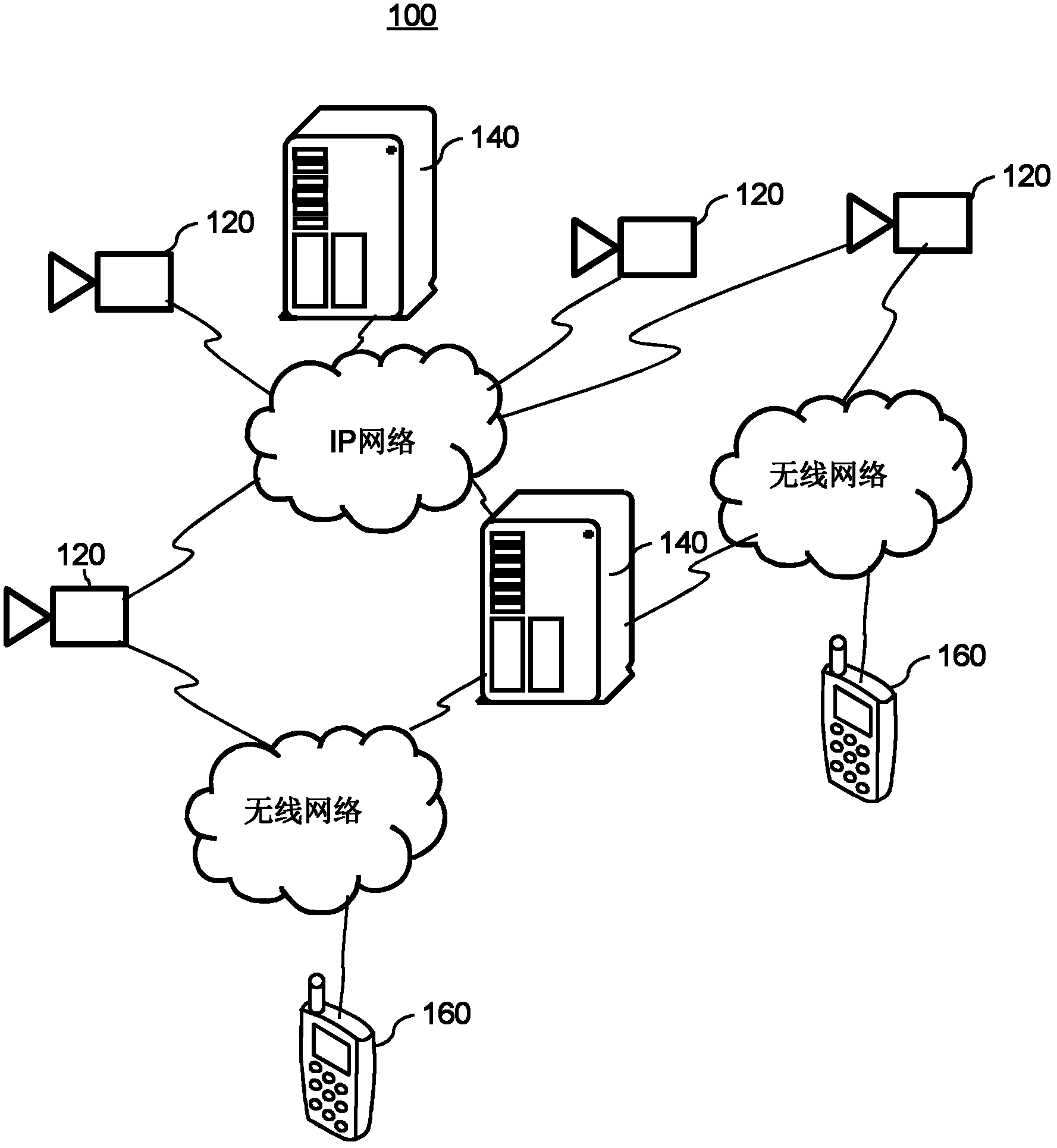
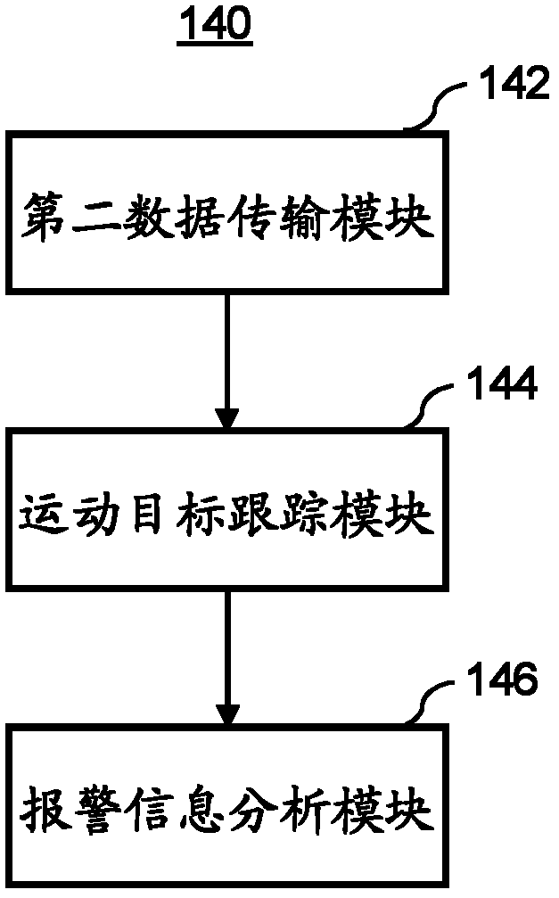
The invention discloses a video monitoring system and a corresponding monitoring method. The video monitoring system comprises one or more front-terminal processing equipment and one or more rear-terminal servers. The front-terminal processing equipment acquires images, performs moving object detection on the images, and selectively sends the images, in which a moving object is detected, to the rear-terminal server when detecting the moving object in the images; and the rear-terminal server performs moving object tracing and alarm behavior analysis on the moving object detected in the images, and gives an alarm when the moving object triggers preset alarm rules. The system adopts the rear-terminal server to accomplish complex computation, such as moving object tracing, alarm behavior analysis and the like, so that the front-terminal processing equipment can be only required to process simpler computation, such as image acquisition and moving object detection, and efficiencies of each equipment can be sufficiently utilized by reasonably matching the configuration and the quantity of hardware in the front-terminal processing equipment and the rear-terminal servers.

Description

【Technical field】 [0001] The invention relates to the technical field of image processing, in particular to a video monitoring system. 【Background technique】 [0002] Video surveillance system is a relatively mature and diverse electronic system used in society. For general video surveillance application scenarios, such as warehouses, factory buildings, etc., or during some periods of time such as night, the monitored scenes rarely change, and few moving objects enter these monitored spaces. There are also some application scenarios that use a static camera to enter the monitoring. The scene image is generally static, that is to say, the image will remain the same image for a long time without obvious changes. [0003] For these video monitoring systems, when the monitoring screen is still, there is a waste of computing resources and storage resources to varying degrees. For example, when the monitoring screen is still, the CPU of the camera is relatively idle; continuous s...

Claims


Application Information

Patent Timeline
IPC IPC(8): H04N7/18G06T7/20G08B13/196H04L29/06
Inventor 高飞
Owner NANJING ZGMICRO CO LTD
Learn More