
Method for remotely and wirelessly controlling illumination end

A wireless control and lighting technology, applied in lighting devices, energy-saving control technology, light sources, etc., can solve problems such as inability to adjust brightness, inability to support incandescent lamps, and inability to control lamp brightness

Active Publication Date: 2011-08-17
TSINGHUA UNIV
View PDF6 Cites 15 Cited by
  • Summary
  • Abstract
  • Description
  • Claims
  • Application Information

AI Technical Summary

Problems solved by technology

[0005] In terms of wireless control of lighting lamps, there is an existing wireless control lamp device that supports remote control of the lights, but cannot control the brightness of the lamps.
In addition, another wireless control lamp device can wirelessly control the induction lamp device, but it cannot provide support for the most common incandescent lamps in the home
[0006] In terms of control circuits, the existing energy-saving controllers used for classroom lighting can only automatically switch on and off the lighting circuit, but cannot adjust the power supply or voltage of the lighting circuit, and cannot adjust the brightness.
[0007] In terms of drive circuits, the automatic adjustment of the brightness of incandescent lamps in AC circuits generally uses silicon controlled rectifiers as the main component, which requires a relatively complex sampling circuit to control its conduction angle, and then achieve the purpose of controlling brightness, but in this way It will bring relatively large harmonic interference to the power grid

Method used


Image

  • Method for remotely and wirelessly controlling illumination end
  • Method for remotely and wirelessly controlling illumination end
  • Method for remotely and wirelessly controlling illumination end

Examples


Embodiment

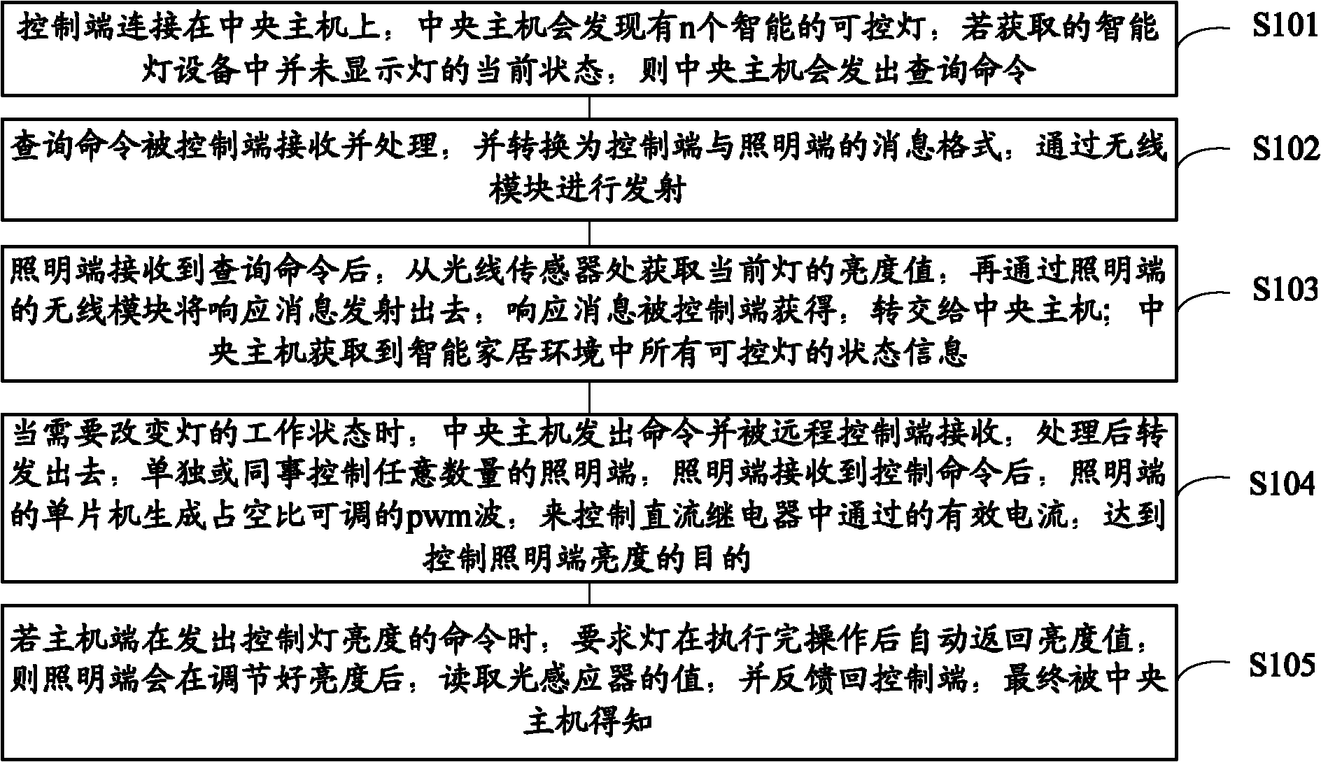
[0028] refer to figure 1 , which shows a flow chart of a method for remote wirelessly controlling the lighting terminal of the present invention, the method specifically includes:

[0029] Step S101, the control terminal is connected to the central host, and the central host will find that there are n intelligent controllable lights. If the acquired smart light device does not display the current status of the lights, the central host will issue a query command,

[0030] Step S102, the query command is received and processed by the control terminal, and converted into a message format between the control terminal and the lighting terminal, and transmitted through the wireless module;

[0031] Step S103, after the lighting terminal receives the query command, it obtains the brightness value of the current light from the light sensor, and then transmits a response message through the wireless module of the lighting terminal, and the response message is obtained by the control te...


PUM


Abstract

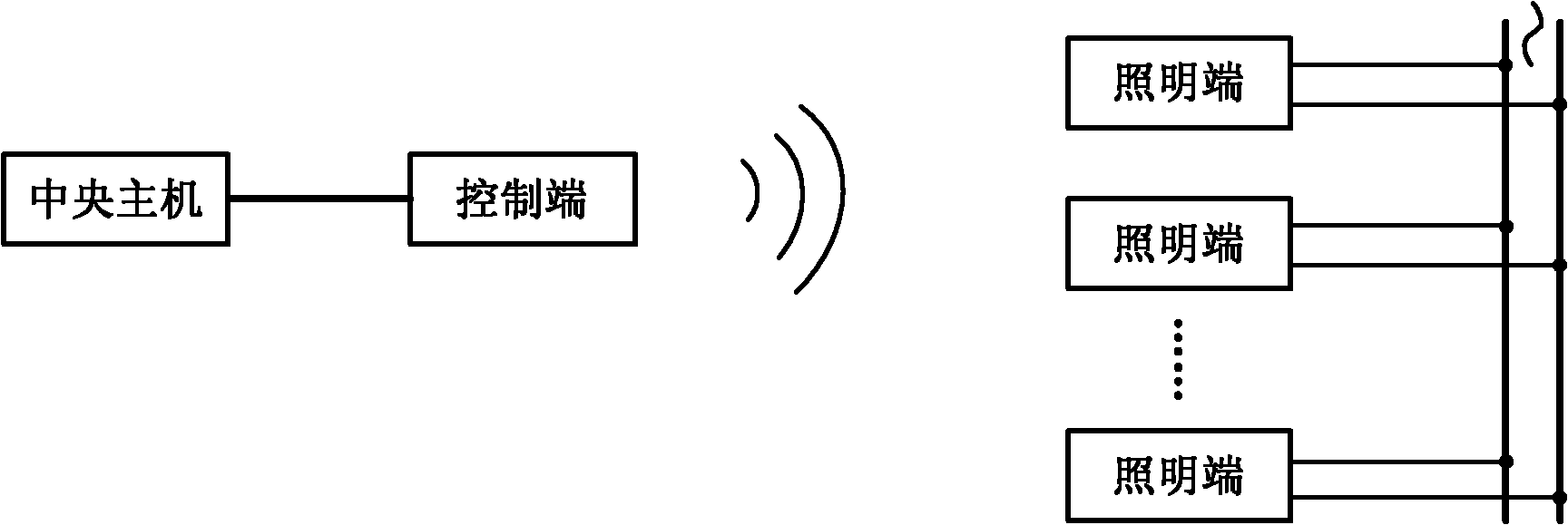
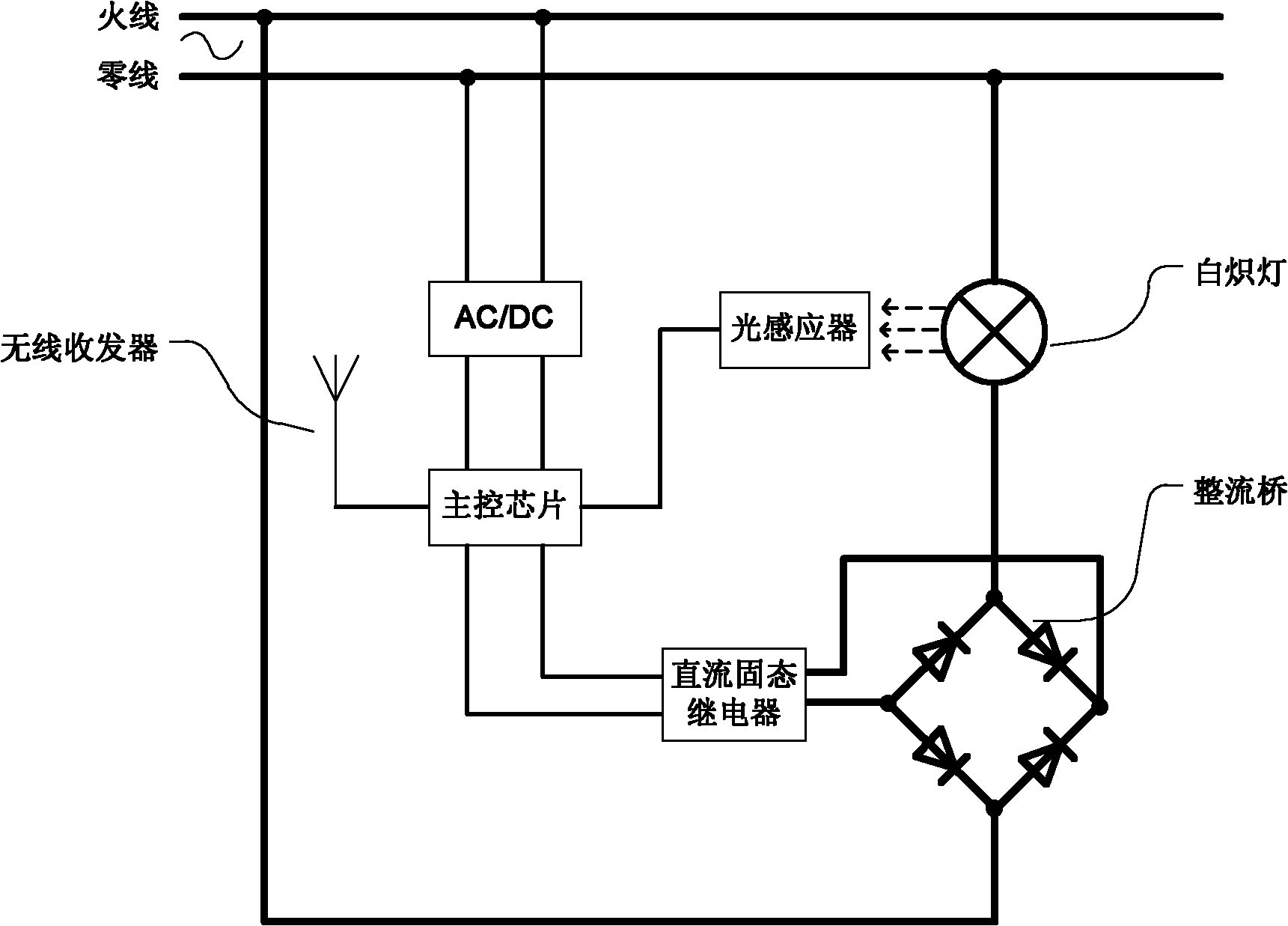
The invention provides a method for remotely and wirelessly controlling an illumination end. The operating environment adopts 220 V alternating current of a family circuit, and mainly comprises an illumination end and a remote control end, wherein the illumination end mainly comprises a single-chip microcomputer, a wireless receiving and transmitting module, an optical inductor, a driving circuit and a filament lamp; the remote control end mainly comprises a single-chip microcomputer, a wireless receiving and transmitting module and a serial module; one remote control end can correspond to a plurality of illumination ends; and a user can remotely turn on or turn off a lamp, remotely control the luminance of the illumination lamp, and obtain the luminance state of the lamp in real time. Simultaneously, the optical inductor module in the illumination device can induce the intensity of peripheral light and automatically adjust the illumination. By connecting the remote control part with a central server in intelligent home environment, and by being matched with corresponding software on the central server, the invention can be served as intelligent equipment to be added to the intelligent home environment, and more conveniently and naturally provide service for the user.

Description

technical field [0001] The invention relates to the technical field of smart home, in particular to a method for remotely controlling a lighting terminal through wireless. Background technique [0002] Smart home technology has made great progress in recent years, which can provide a more convenient and harmonious living environment. In the smart home environment, there will be one or more computers as the central server to control the interconnection of all devices, and a communication network will be established to provide the necessary access for the communication of home devices. Under the coordination of the central server, all smart devices work in an orderly manner, and can monitor and remotely control the status of all home appliances and other smart devices on the home network. [0003] Lighting is a very important part of the home environment. Intelligent lighting equipment allows users to remotely control and monitor their working status, and can adaptively chang...

Claims


Application Information

Patent Timeline
IPC IPC(8): H05B37/02G08C17/02
CPCY02B20/48Y02B20/40
Inventor 史元春秦永强索岳
Owner TSINGHUA UNIV
Learn More