Oil separation system structure of screw air compressor

An air compressor oil and sub-system technology, used in mechanical equipment, machines/engines, liquid fuel engines, etc., can solve the problems of cumbersome installation, increase leakage points, unfavorable installation, etc., and save labor, pipes and joints. Effect

Inactive Publication Date: 2011-08-24
SHANGHAI INGERSOLL RAND COMPRESSOR CO LTD
View PDF2 Cites 7 Cited by
  • Summary
  • Abstract
  • Description
  • Claims
  • Application Information

AI Technical Summary

Problems solved by technology

[0003] At present, the structure of the oil separation system of screw air compressors on the market generally adopts the structure of installing a single component. The installation design of a single component will lead to too many pipe connections, too many joint connections, and increase leakage points. It is not conducive to installation, the installation is very cumbersome and wasteful

Method used


Image

  • Oil separation system structure of screw air compressor
  • Oil separation system structure of screw air compressor
  • Oil separation system structure of screw air compressor

Examples


Embodiment

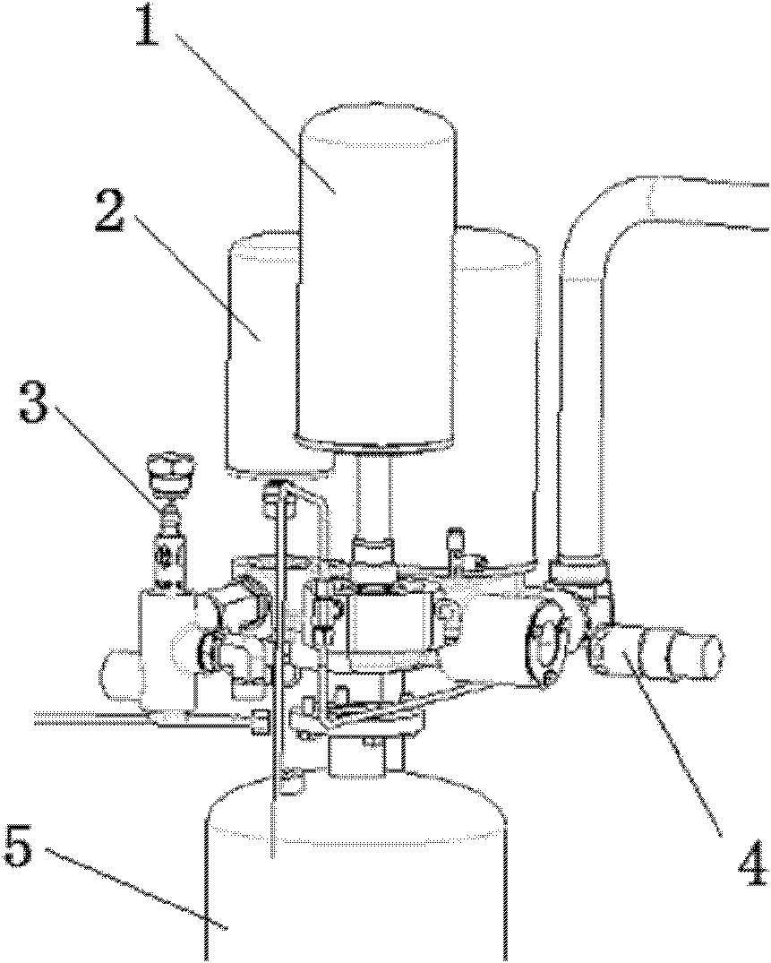
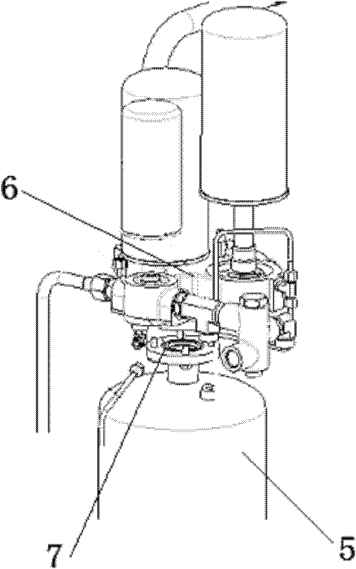
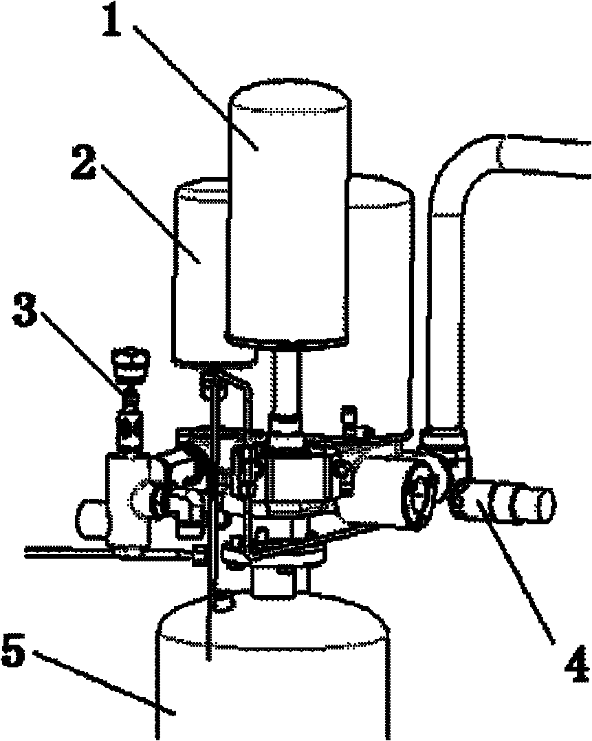
[0016] Such as figure 1 with figure 2 As shown in the figure, a combination valve 6 is included in the figure, an oil separation barrel 5 is placed under the combination valve 6, an O-ring 7 with a sealing effect is arranged at the connection between the combination valve 6 and the oil separation barrel 5, and an O-ring 7 with sealing effect is arranged on the combination valve 6. Oil separator 1, oil filter 2, the lower port of oil separator 1 and the lower port of oil filter 2 are respectively connected to combined valve 6, combined valve 6 is connected to a temperature control valve spool 3, and one side of combined valve 6 is connected to a minimum pressure valve 4.

[0017] The oil separator core 1 and the oil filter core 2 are arranged vertically and parallelly on the combined valve.

[0018] The structure of the oil separation system in this embodiment is mainly used in V series 15-37KW air compressors.

[0019] The present invention adopts an integral valve body on...


PUM


Abstract

The invention discloses an oil separation system structure of a screw air compressor. The structure comprises a combination valve, an oil separation barrel is arranged below the combination valve, an O-shaped ring with sealing effect is arranged at the joint of the combination valve and the oil separation barrel, an oil separation core and an oil filtration core are arranged above the combination valve, the lower port of the oil separation core and the lower port of the oil filtration core are connected with the combination valve respectively, the combination valve is connected with a temperature control valve core, and one side of the combination valve is connected with a minimum pressure valve. After the combination valve is adopted, the oil separation core, the oil filtration core, the minimum pressure valve, the temperature control valve and the like can be easily arranged on the combination valve, so that pipelines and joints are saved and manpower is saved at the same time.

Description

technical field [0001] The invention relates to the field of screw air compressors, in particular to an oil separation system structure of a screw air compressor. Background technique [0002] Screw air compressors (air compressors) drive compression components at the optimum speed for the application through an efficient transmission system. Screw air compressors are widely used due to their advantages of high stability, high efficiency, low vibration and low noise. [0003] At present, the structure of the oil separation system of screw air compressors on the market generally adopts the structure of installing a single component. The installation design of a single component will lead to too many pipe connections, too many joint connections, and increase leakage points. It is not conducive to installation, and the installation is very cumbersome and wasteful. Contents of the invention [0004] The purpose of the present invention is to provide a screw air compressor oi...

Claims


Application Information

Patent Timeline
Patent Type & Authority Applications(China)
IPC IPC(8): F04C29/02
Inventor 马晓东李迟珺
Owner SHANGHAI INGERSOLL RAND COMPRESSOR CO LTD
Why Eureka
Try Eureka