A gas fluid mixture self-priming pump

A gas-liquid mixed transport and self-priming pump technology, applied in the field of hydraulic machinery, can solve the problems of small displacement, unfavorable energy saving, complicated operation, etc., and achieve the effects of strong self-priming ability, improved service life, and convenient installation and maintenance.

Inactive Publication Date: 2012-11-28
长春泵业有限公司
View PDF0 Cites 0 Cited by
  • Summary
  • Abstract
  • Description
  • Claims
  • Application Information

AI Technical Summary

Problems solved by technology

[0002] At present, there are many styles of self-priming pumps on the market, some are water ring type: but their efficiency is low, the volume is large, and the displacement is small; Filling with water is also not suitable for large displacement; some adopt double-drive type: that is, first use one power source to pump air, and then start another power source to drain water. The disadvantages are obvious, the operation is cumbersome, and it is not conducive to energy saving; Self-priming pump: After the pumping is completed, the floating ball mechanism is still sucked at the valve port, and cannot fall back to its original position for a long time, and the suction channel is always closed, making it difficult for the pump to run again, etc.

Method used


Image

  • A gas fluid mixture self-priming pump
  • A gas fluid mixture self-priming pump
  • A gas fluid mixture self-priming pump

Examples


Embodiment Construction

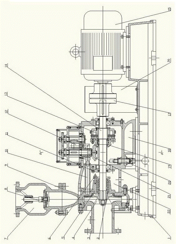
[0019] The present invention comprises Roots pump 12, motor 15, is characterized in that: the shaft of motor 15 is connected with rotor 14 through coupling 17;

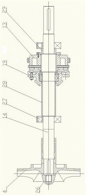
[0020] The rotor 14 passes through the spindle box 18 and the mechanical seal chamber 22, and extends to the inlet section 3, and the rotor 14 is installed with the impeller 4 through the impeller nut 26 at the end of the inlet section 3;

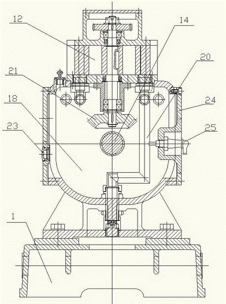
[0021] The rotor 14 is connected to the shell of the main shaft box 18 through bearings, and is sealed by the bearing cover 11. A Roots pump 12 is installed in the main shaft box 18, and a driven bevel gear 21 is installed on the shaft of the Roots pump 12. On the rotor 14 Clutch 13 is installed on it, and driving bevel gear 19 is installed on the front end of clutch 13, and driving bevel gear 19 meshes with driven bevel gear 21;

[0022] The inlet of the Roots pump 12 is connected to the suction pipe 10, the other end of the suction pipe 10 communicates with the inlet section 3,...


PUM


Abstract

The invention, which belongs to the hydro-machinery field, discloses a gas fluid mixture self-priming pump. The gas fluid mixture self-priming pump provided in the invention is equipped with an independent water pump, an independent air pump, and an engaging and disengaging device that can perform automatic engaging and disengaging actions. The gas fluid mixture self-priming pump in the inventionincludes a Roots pump and a motor. A shaft of the motor is connected to the rotor through a shaft coupling. A rotor goes through a headstock and a mechanical seal chamber and extends to an entrance of the pump. The rotor is equipped with an impeller. The rotor is connected to a housing of the headstock through the bearing. The Roots pump is disposed in the main headstock. A driven bevel gear, which is installed on a shaft of the Roots pump, is engaged with a drive bevel gear which is installed on the front end of a clutch. An inlet of the Roots pump is connected to one end of an induction pipe and the other end of the induction pipe communicates with the entrance of the pump. An outlet of the Roots pump is connected to the escape pipe and the escape pipe extends out of the headstock; the outlet valve component equipped with a back valve inside is disposed on the scroll case. The motor, the mechanic seal chamber and the headstock are all arranged on the pedestal. The gas fluid mixture self-priming pump provided in the invention does not make comparatively loud noise in running. The induction pipe and the escape pipe of the pump are concealed, thereby forming a structure belonging to a concealed type. And the engaging and disengaging actions can be performed by automatically controlling the engaging and disengaging device according to the running condition of the pump. Therefore, the service life time of the gas fluid mixture self-priming pump is prolonged.

Description

technical field [0001] The invention belongs to the field of hydraulic machinery. Background technique [0002] At present, there are many styles of self-priming pumps on the market, some are water ring type: but their efficiency is low, the volume is large, and the displacement is small; Filling with water is also not suitable for large displacement; some adopt double-drive type: that is, first use one power source to pump air, and then start another power source to drain water. The disadvantages are obvious, the operation is cumbersome, and it is not conducive to energy saving; Self-priming pump: After the pumping is completed, the floating ball mechanism is still sucked at the valve port, and cannot fall back to its original position for a long time, and the suction channel is always closed, making it difficult for the pump to run again. Contents of the invention [0003] The object of the present invention is to provide a self-priming pump for gas-liquid mixed deliver...

Claims


Application Information

Patent Timeline
Patent Type & Authority Patents(China)
IPC IPC(8): F04D9/04
Inventor 葛荀
Owner 长春泵业有限公司
Why Eureka
Try Eureka