Pressure induction type flow switch

A flow switch and inductive technology, which is applied in the field of flow measurement devices, can solve problems such as difficult detection, drop-shaped flow leakage, and inability to detect, and achieve the effects of convenient maintenance and use, reduced equipment costs, and accurate and reliable detection results

Active Publication Date: 2011-08-24
704TH RES INST OF CHINA SHIPBUILDING IND CORP
View PDF5 Cites 5 Cited by
  • Summary
  • Abstract
  • Description
  • Claims
  • Application Information

AI Technical Summary

Problems solved by technology

[0003] Mechanical flow switch - its characteristic is that the sensing element (such as reed or spool, etc.) is inserted into the pipeline of the valve remote control hydraulic system. When the liquid in the pipeline flows, the flowing liquid impacts the sensing element and makes the sensing element Generate a certain amount of displacement, and then touch the electrical component to send a signal; but this kind of flow switch needs enough flow to generate the displacement of the above-mentioned sensing element, and it is difficult to detect small flow, especially droplet flow leakage;
[0004] Electronic flow switch - its characteristic is to use the principle of heat conduction for flow detection, that is, the heat conduction flow switch judges whether the fluid is flowing by detecting whether the heat contacted by the detection element (such as a heating probe) and the measured fluid is taken away by the fluid. Obviously, this structure also requires sufficient flow to be effective, and it cannot detect small flow and drop-shaped flow leakage; similar devices that use ultrasonic principles to detect flow also require a certain value of flow; the prices of the above-mentioned electronic flow switches are all more expensive

Method used


Image

  • Pressure induction type flow switch
  • Pressure induction type flow switch
  • Pressure induction type flow switch

Examples


Embodiment Construction

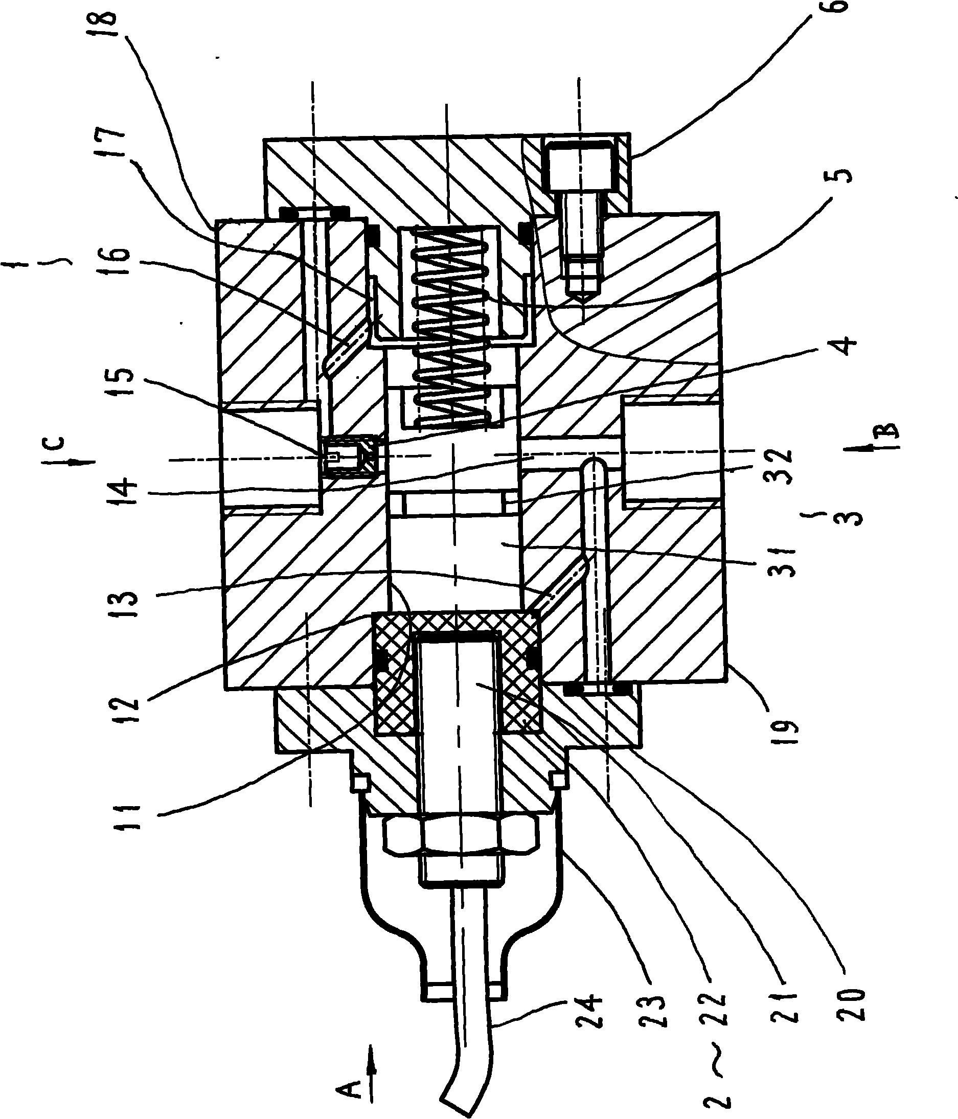
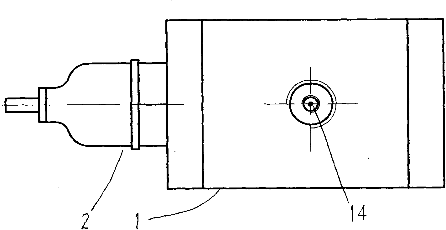
[0016] refer to figure 1 , The pressure-sensing flow switch includes a switch body 1, a proximity switch assembly 2, a sensing piston 3, a damper 4, a spring 5 and a right end cover 6.

[0017] The switch body 1 is a block, part of which has a working chamber 11 in the longitudinal direction. The working chamber 11 is a round hole for accommodating the sensing piston 3. The surface of the round hole is finely processed to ensure that the sensing piston 3 can move freely. Move to form a sliding fit, and can ensure good sealing between the mating surfaces of the two; the working chamber 11 and other related parts of the configuration together form a sealed working chamber;

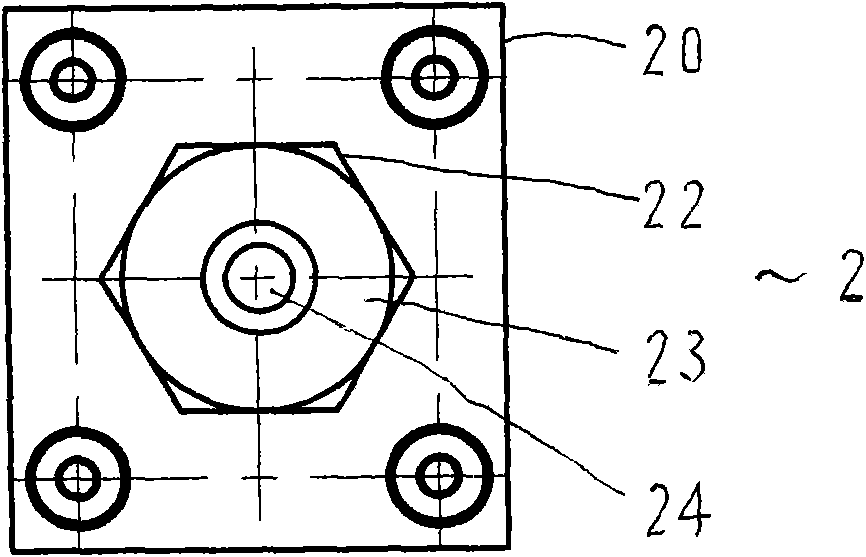
[0018] The left chamber 12 in the switch body 1 is a part of the left side of the working chamber 11, and is a sealed space jointly formed by the working chamber 11, the bottom surface of the left end cover 20 of the proximity switch assembly 2, the left end surface of the sensing piston 3 and the correspond...


PUM


Abstract

The invention relates to a pressure induction type flow switch, which is mainly used for detecting micro flow and dropwise leakage. In the adopted technical scheme, a switch body of the switch comprises a working cavity, an induction piston which is in sliding fit is arranged in the cavity, a proximity switch component and a right end cover are fixedly arranged at two ends of the switch body respectively, a left cavity is formed between the proximity switch component and the induction piston, a right cavity is formed between the right end cover and the induction piston, an inlet oil guide hole, an inlet, an outlet and a outlet oil guide hole are further arranged on the switch body, the inlet oil guide hole is connected with the left cavity and the inlet, the outlet oil guide hole is connected with the outlet and the right cavity, a damper is arranged between the working cavity and the outlet, and a spring is arranged between the induction piston and the right end cover. The pressure induction type flow switch can be used for detecting the micro liquid flow and leakage of pipelines in switch control loops of valve remote control systems.

Description

Technical field: [0001] The invention relates to a flow measuring device, in particular to a device for detecting liquid flow in a hydraulic system. Background technique: [0002] In the hydraulic system, there are many occasions where it is necessary to detect whether the liquid in the system is flowing, whether there is leakage, etc., without the need to specifically measure its flow or flow rate, especially in the valve remote control system, in some explosion-proof occasions, it is not allowed to use electronic sensors It is installed on the valve driver to directly measure the running state of the driver. Only indirect methods can be used to judge whether the driver is in motion. It is judged by whether there is liquid flow in the detection system. Usually, a flow switch is used as a detection and judgment device. Existing There are two types of flow switches: [0003] Mechanical flow switch - its characteristic is that the sensing element (such as reed or spool, etc.)...

Claims


Application Information

Patent Timeline
Patent Type & Authority Applications(China)
IPC IPC(8): H01H35/38
Inventor 张中荣孔凡会邵昱张海波
Owner 704TH RES INST OF CHINA SHIPBUILDING IND CORP
Why Eureka
Try Eureka