Single-phase permanent-magnet synchronous motor for efficient fan
A technology for single-phase permanent magnet and synchronous motors, applied to synchronous motors with stationary armatures and rotating magnets, magnetic circuit rotating parts, magnetic circuit shape/style/structure, etc., can solve the problem of active power consumption and motor efficiency Low and other problems, to achieve the effect of reducing excitation loss and improving motor efficiency
- Summary
- Abstract
- Description
- Claims
- Application Information
AI Technical Summary
Problems solved by technology
Method used
Image

Examples
Embodiment 1
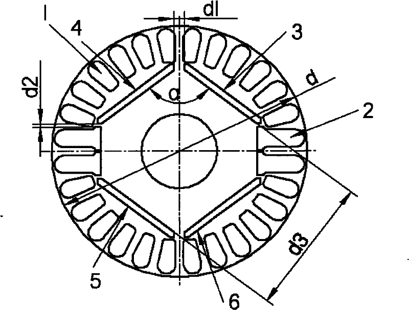
[0014] Such as figure 1 As shown, a single-phase permanent magnet synchronous motor for a high-efficiency fan includes a stator and a rotor. Twenty-four squirrel cage guide grooves a1, four squirrel cage guide grooves b2 and four squirrel cage guide grooves are provided on the rotor core. A magnet insertion slot: including a magnet insertion slot a3, a magnet insertion slot b4, a magnet insertion slot c5 and a magnet insertion slot d6, the squirrel cage guide bar slot a1 and the squirrel cage guide bar slot b2 are arranged on the periphery of the rotor core, The four squirrel-cage bar slots b2 are arranged in pairs on opposite ends of the rotor iron core diameter, and the magnet insertion slots are symmetrically arranged on the squirrel-cage bar slots a1 and squirrel-cage bar slots on the rotor iron core On the inner side of b2, permanent magnets are placed in the magnet insertion slots, among which permanent magnets of the same polarity are inserted in the magnet insertion sl...
Embodiment 2
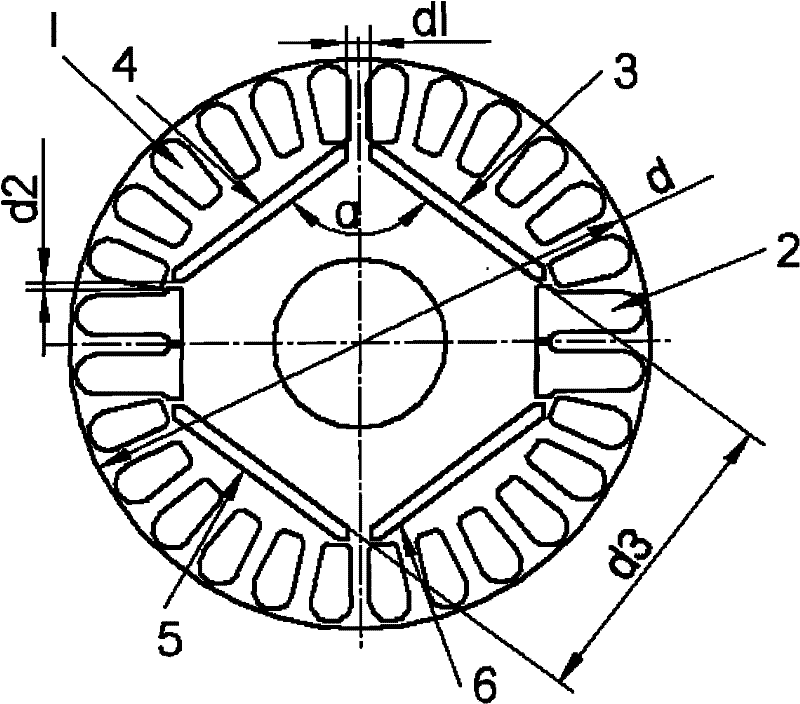
[0016] A single-phase permanent magnet synchronous motor for a high-efficiency fan, including a stator and a rotor. The rotor core is provided with eight squirrel-cage bar slots a, two squirrel-cage bar slots b, and two magnet insertion slots. The squirrel cage guide bar groove a and the squirrel cage guide bar groove b are arranged on the periphery of the rotor core, and the two squirrel cage guide bar grooves b are respectively arranged on opposite ends of the rotor iron core diameter, and the magnet insertion slot It is arranged symmetrically on the inner side of the squirrel cage guide bar groove a and the squirrel cage guide bar groove b on the rotor core, and permanent magnets are placed in the magnet insertion slots, and permanent magnets with opposite polarities are respectively inserted in the two magnet insertion slots. The angle α between the two magnet insertion slots is 180 degrees, the distance d1 between the adjacent top ends is 3 mm, and the distance d2 between ...
Embodiment 3
[0018] A single-phase permanent magnet synchronous motor for a high-efficiency fan, including a stator and a rotor. The rotor core is provided with thirty-six squirrel-cage bar slots a, eight squirrel-cage bar slots b, and eight magnet inserts The squirrel cage guide bar slot a and the squirrel cage guide bar slot b are arranged on the periphery of the rotor core, and the eight squirrel cage guide bar slots b are divided into four groups in pairs, and are respectively arranged on two sides of the rotor iron core. On the opposite ends of the vertical diameter, the magnet insertion slots are arranged symmetrically on the inside of the squirrel cage guide bar slot a and the squirrel cage guide bar slot b on the rotor iron core, permanent magnets are placed in the magnet insertion slots, each magnet insertion slot and its two sides Adjacent magnet insertion slots, one side inserts permanent magnets of the same polarity, and the other side inserts permanent magnets of opposite polar...
PUM
 Abstract
Description
Claims
Application Information
 - R&D
- Intellectual Property
- Life Sciences
- Materials
- Tech Scout
- Unparalleled Data Quality
- Higher Quality Content
- 60% Fewer Hallucinations
Browse by: Latest US Patents, China's latest patents, Technical Efficacy Thesaurus, Application Domain, Technology Topic, Popular Technical Reports.
© 2025 PatSnap. All rights reserved.Legal|Privacy policy|Modern Slavery Act Transparency Statement|Sitemap|About US| Contact US: help@patsnap.com