Rolling shaft type zipper puller

A zipper head and roller technology, applied in the field of zippers, can solve the problems of inconsistent specifications of zipper heads, not easy to use interchangeably, and short life of zippers, etc., and achieve the best sliding degree, prevent tooth explosion, and prolong the sliding degree

Active Publication Date: 2013-01-30
王联洲
View PDF5 Cites 0 Cited by
  • Summary
  • Abstract
  • Description
  • Claims
  • Application Information

AI Technical Summary

Problems solved by technology

However, under these conditions, the specifications of the zipper pullers are not uniform, and it is not easy to use them interchangeably. In particular, professional zipper pullers must be tailored for each zipper assembly factory, which is difficult to manage.
Although many manufacturers have tolerance control on the internal dimensions of the zipper slider corresponding to the specifications of the zipper tape and sprockets, in use, often due to the friction between the zipper puller and the sprockets at the corners, it is easy to be damaged due to frequent use. The stitches sewn on the chain teeth are worn out or the shape of the chain teeth and the zipper head are worn, resulting in the short life of the entire zipper and scrapping

Method used


Image

  • Rolling shaft type zipper puller
  • Rolling shaft type zipper puller
  • Rolling shaft type zipper puller

Examples


Embodiment Construction

[0042] The present invention will be further described below in conjunction with the accompanying drawings and specific embodiments.

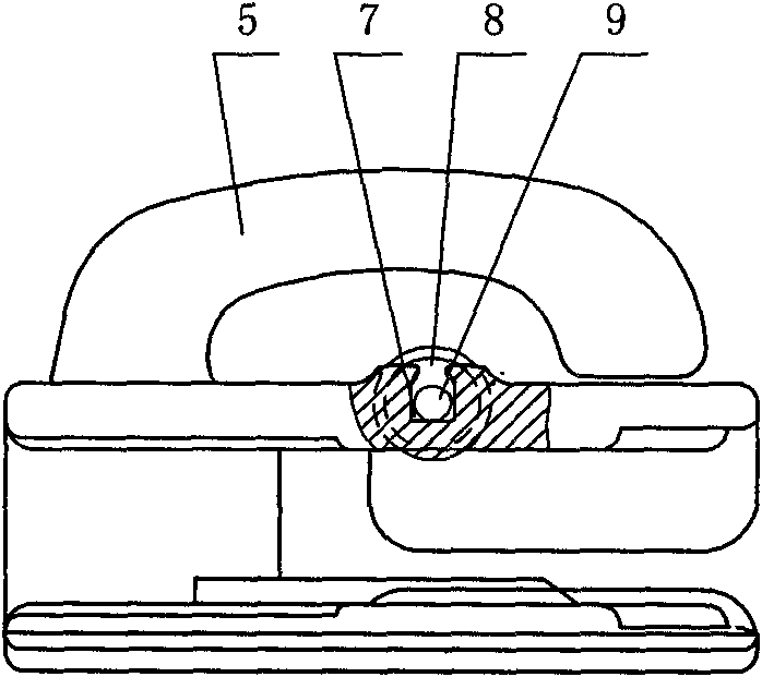
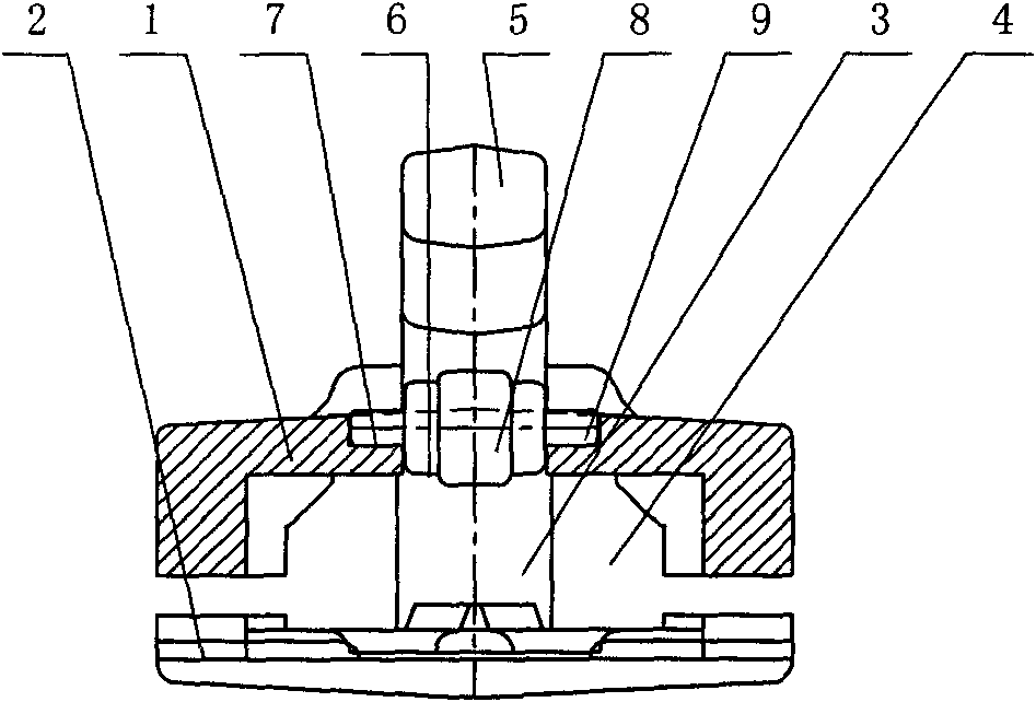
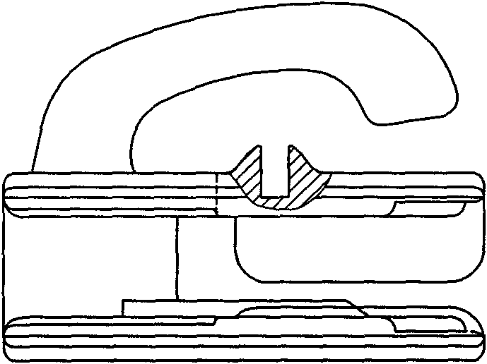
[0043] Roller zipper pulls such as figure 1 , figure 2 As shown, it includes an upper guard plate 1, a lower guard plate 2, and a guide base 3 connecting the upper guard plate 1 and the lower guard plate 2, and the upper guard plate 1 and the lower guard plate 2 form an inner In the space 4, a connection portion 5 for installing a pull tab is provided above the upper guard plate 1, a through groove 6 is provided near the middle of the upper guard plate 1, and opposite shafts are respectively provided on both sides of the through groove 6. Seat groove 7 such as image 3 As shown, the through groove 6 communicates downward with the internal space 4 of the zipper head, at least one roller 8 is arranged in the through groove 6 and the shaft seat groove 6 on both sides of the through groove 6, and the roller The lower surface of 8 slightly expos...


PUM


Abstract

The invention discloses a rolling shaft type zipper puller, aiming to provide a rolling shaft type zipper puller which has the advantages of simple structure, strong commonality and long service life and is convenient to manufacture. The rolling shaft type zipper puller comprises an upper backplate, a lower backplate and a guiding base center, wherein the guiding base center is connected between the upper backplate and the lower backplate; an inner space is formed between the upper backplate and the lower backplate; and a junction part for installing a zipper pull is arranged above the upper backplate. The rolling shaft type zipper puller is characterized in that the position close to the middle of the upper backplate is provided with a through groove, two sides of the through groove are respectively provided with opposite shaft base grooves; the through groove is downwards communicated with the inner space of the zipper puller; at least one rolling shaft is arranged in the through groove and the shaft base grooves on two sides of the through groove; the lower surface of the rolling shaft is slightly exposed out of the inner space of the zipper puller; the exposing part corresponds to the hinged tooth position of the left chain tooth and the right chain tooth of the zipper; the lower surface of the rolling shaft is next to or adjacent to the chain tooth; the shaft necks of the two ends of the rolling shaft are placed in the shaft base grooves; and the rolling shaft rolls in the shaft base grooves.

Description

technical field [0001] The present invention relates to slide fasteners, and more particularly to a roller type slide fastener puller. Background technique [0002] The basic functional design of the zipper puller comes from the principle of gears meshing with each other. The left and right chains are compared to soft equidistant racks, and the frame of the zipper puller structure and the front-end partition bar make the chains open and close. When each sprocket of the chain engages with each other in the internal space of the zipper head frame. When the zipper head moves up and down, the tooth heads of the left and right chain teeth are in the process of meshing with each other. If the tooth heads push against each other, the sliding will not be good. If the horizontal position of the tooth heads is asymmetrical, it will easily cause poor meshing. The situation of bursting teeth appears. In order to prevent the above disadvantages, most manufacturers strictly control the ...

Claims


Application Information

Patent Timeline
Patent Type & Authority Patents(China)
IPC IPC(8): A44B19/26
Inventor 王联洲
Owner 王联洲
Why Eureka
Try Eureka