Three-coordinate galvanometer scanning laser processing head

A laser processing head and galvanometer scanning technology, which is applied in metal processing equipment, laser welding equipment, manufacturing tools, etc., can solve the problems of lack of modularization and independent interface characteristics, difficulty in realizing complex curved surface workpieces, and difficulty in disassembly and installation. Achieve the effect of simple combined processing, compatible functions, and not easy to disassemble and install

Active Publication Date: 2011-08-31
武汉飞能达激光技术有限公司
View PDF8 Cites 23 Cited by
  • Summary
  • Abstract
  • Description
  • Claims
  • Application Information

AI Technical Summary

Problems solved by technology

[0005] However, in the current galvanometer scanning laser processing equipment, the structure of the galvanometer scanning laser processing head is relatively simple. In addition to the XY two-axis laser galvanometer system, there are only some auxiliary mechanisms such as dust removal and CCD processing monitoring. The two-dimensional laser galvanometer system is designed to be fixedly connected to the multi-axis CNC machine tool. Because it does not have the characteristics of modularization and independent interface, it is not easy to disassemble and install, and the adjustment of the focal length must rely on the Z-axis motion mechanism of the multi-axis CNC machine tool. Functional correlation High precision, it is difficult to realize the processing requirements of complex curved surface workpieces that require frequent adjustment of the processing focal length in real time
Furthermore, there is no literature report on the galvanometer scanning laser processing head with integrated processing focal length measurement and adjustment functions.

Method used


Image

  • Three-coordinate galvanometer scanning laser processing head
  • Three-coordinate galvanometer scanning laser processing head

Examples


Embodiment Construction

[0016] Typical implementations of the present invention will be described in detail below with the help of drawings and examples.

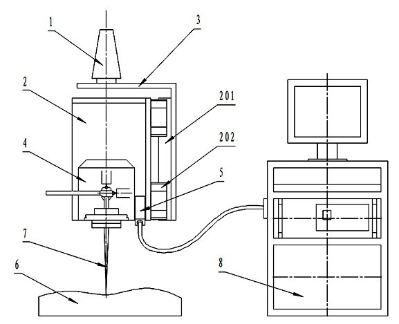
[0017] The three-coordinate galvanometer scanning laser processing head of the present invention has a structure such as figure 1 As shown, it includes: clamping mechanism 1, Z-axis moving mechanism 2, bracket 3, XY two-axis laser vibrating mirror system 4, laser displacement sensor 5 and control system 8. The Z-axis moving mechanism 2 , the XY two-axis laser vibrating mirror system 4 , and the laser displacement sensor 5 are all electrically connected to the control system 8 . The bottom of the clamping mechanism 1 is installed on the bracket 3, which is used to install the laser processing head on the multi-axis linkage CNC machine tool; the Z-axis moving mechanism 2 is also installed on the bracket 3, which is used to adjust the XY two-axis laser galvanometer system The Z-axis position, which can move up and down along the Z-axis direction; th...


PUM


Abstract

The invention provides a three-coordinate galvanometer scanning laser processing head, which comprises an XY two-axis laser galvanometer system, a clamping mechanism, a Z-axis moving mechanism, a laser displacement sensor and a control system, wherein the Z-axis moving mechanism comprises a fixed part and a moving part, and the clamping mechanism is fixedly mounted on the fixed part of the Z-axis moving mechanism; and the XY two-axis laser galvanometer system and the laser displacement sensor are fixedly mounted on the moving part of the Z-axis moving mechanism, and the laser displacement sensor, the Z-axis moving mechanism and the XY two-axis laser galvanometer system are all electrically connected with the control system. The laser processing head has the function of dynamic focal length setting, and has an independent and compact structure; the laser processing head has the broach interface design of a standard numerically-controlled machine tool, which enables the laser processing head to be easily assembled for processing with commercialized multi-axis synchronous numerically-controlled machine tools of a three-axis type, a five-axis type, and the like; and technological flexibility is greatly enhanced, and a conventional multi-axis synchronous numerically-controlled machine tool can be conveniently changed into a galvanometer scanning laser processing machine tool with compatible functions, thereby the three-coordinate galvanometer scanning laser processing head has important practical value.

Description

technical field [0001] The invention belongs to the application field of laser processing, in particular to a three-coordinate vibrating mirror scanning laser processing head. Background technique [0002] In recent years, the laser processing technology based on galvanometer scanning (hereinafter referred to as galvanometer scanning laser processing) is due to its high efficiency, high precision, non-contact, high degree of flexibility, and strong material adaptability (machinable superhard, ultrabrittle , ultra-thin and other special materials) and other characteristics, so that it has been widely used in the field of precision manufacturing. [0003] The galvanometer scanning laser processing equipment generally includes a laser, a light guide path, a galvanometer scanning laser processing head, and a machine tool. The system principle is: the laser beam output from the laser resonator passes through the light guide path to complete the beam expansion alignment After str...

Claims


Application Information

Patent Timeline
Patent Type & Authority Applications(China)
IPC IPC(8): B23K26/08B23K26/04
Inventor 曹宇曾晓雁段军王泽敏李祥友高明胡乾午刘建国
Owner 武汉飞能达激光技术有限公司
Why Eureka
Try Eureka