Tool device and method for machining large turbine blade combined partition plate

A steam turbine blade and processing method technology, which is applied in metal processing equipment, manufacturing tools, arc welding equipment, etc., can solve the problems of difficult weld formation, increased difficulty of arc welding with electrodes, and welding bumps, and achieves the convenience of reaching the molten pool close to the level Effect

Inactive Publication Date: 2020-12-08
无锡市润和机械有限公司 +1
View PDF10 Cites 0 Cited by
  • Summary
  • Abstract
  • Description
  • Claims
  • Application Information

AI Technical Summary

Problems solved by technology

[0003] The existing processing method adopts the platform plate to fix the welding position of the blade disk and the blade. When the angle of the welding line of the blade combination partition is too large, the platform plate cannot adjust the angle of the blade disk blade, so vertical welding has to be used. , Overhead welding, manual operation of electrode arc welding is more difficult, resulting in unguaranteed welding quality, difficulty in forming the weld seam, easy to produce weld bumps on the surface of the weld seam, and even collapse; and the flat plate of the fixed blade combination partition cannot rotate by itself. Therefore welding efficiency is lower
Welding quality cannot be guaranteed

Method used


Image

  • Tool device and method for machining large turbine blade combined partition plate
  • Tool device and method for machining large turbine blade combined partition plate
  • Tool device and method for machining large turbine blade combined partition plate

Examples


Embodiment Construction

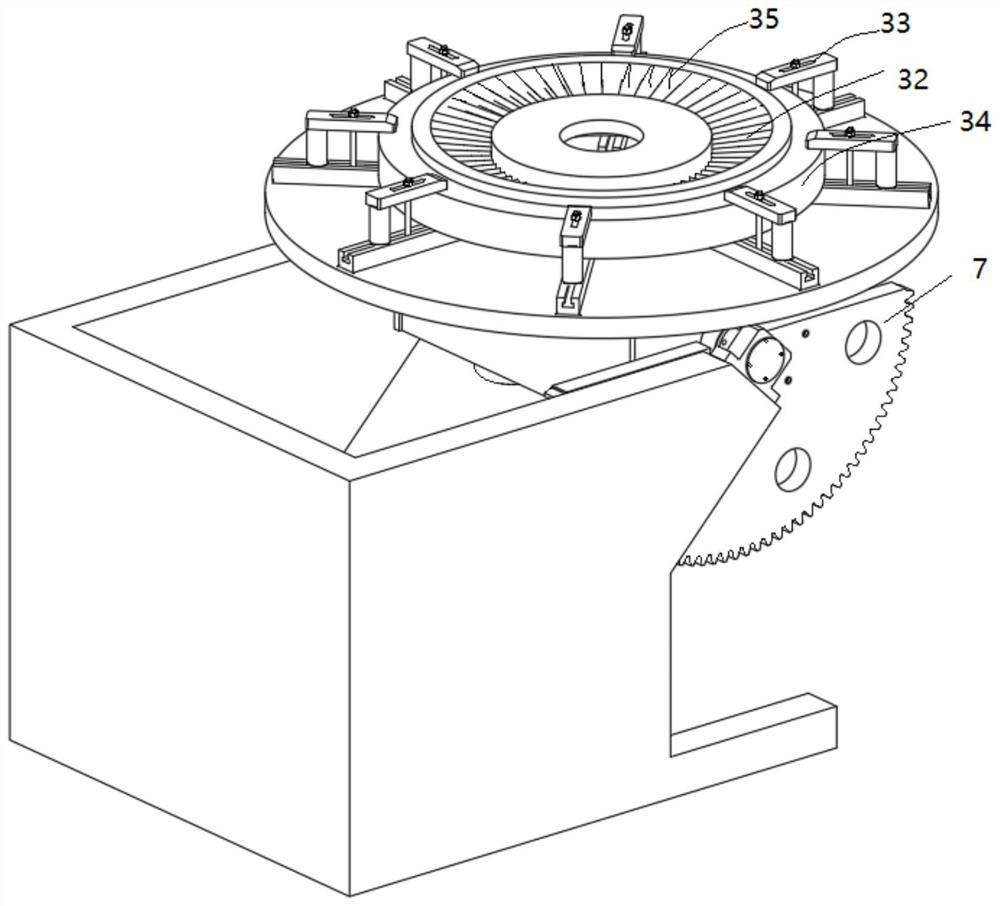
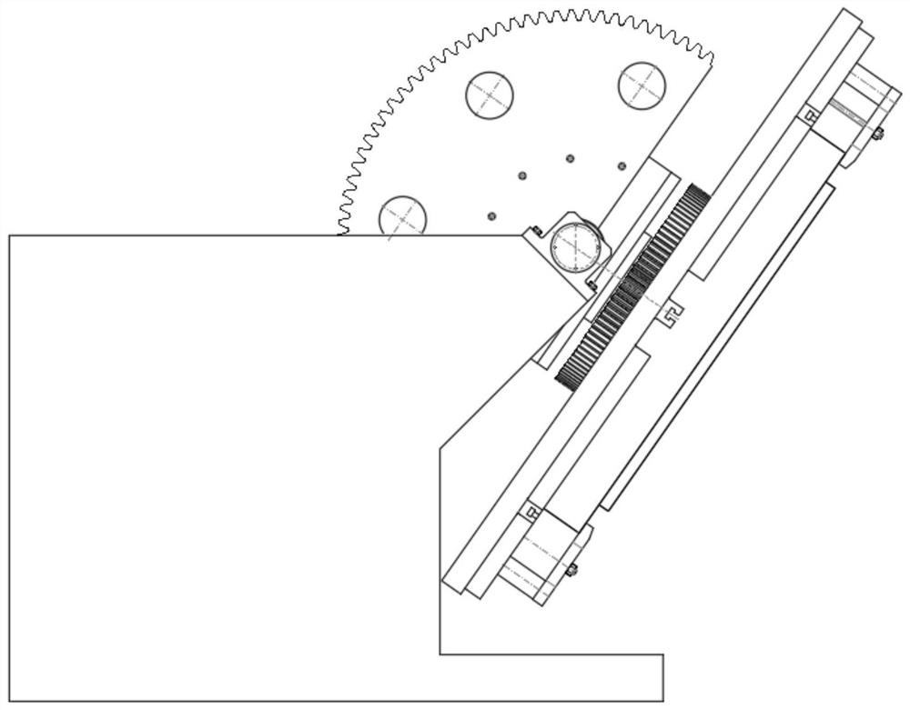
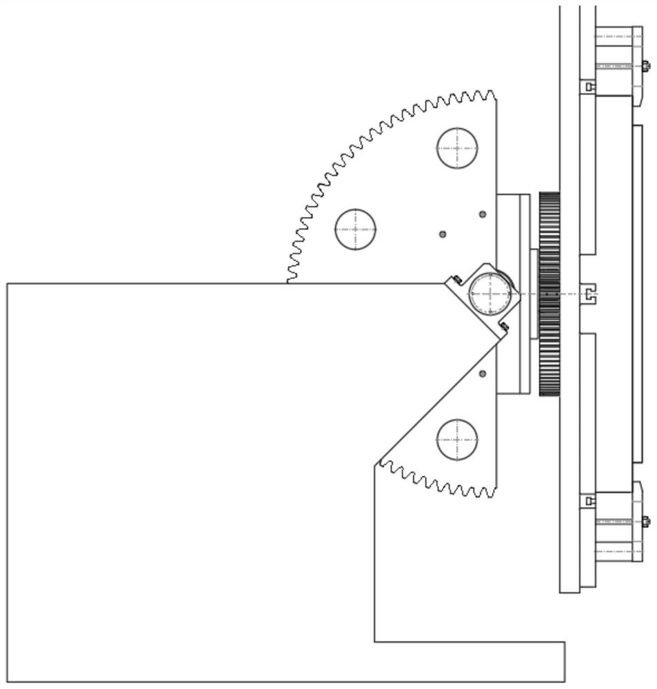
[0018] As shown in the figure, the present invention includes a base 1 and a rotating bracket 8. The inside of the base 1 is provided with a transmission motor 2. The transmission motor 2 is connected to the reducer 5 through the motor coupling 3 and the reducer coupling 4. The reducer 5. The other end is provided with a reducer gear 6. The reducer gear 6 drives the large gear 7 through meshing. The rotation range of the large gear 7 is controlled by the limit switch 9. The large gear 7 is fixed on the rotating bracket 8 by bolts. The rotating bracket 8 is equipped with a Transmission shaft 19, transmission shaft 19 is fixed with transmission bearing 15 by lock nut 14, is provided with transmission bearing spacer 16 in transmission bearing 15; Transmission shaft 19 one ends are provided with transmission gear 18, and transmission gear 18 is fixed on the turntable 10 by bolt, and turntable 10 is fixed on the transmission shaft 19 by turntable end cover 20; And rotary shaft 25, o...


PUM

PropertyMeasurementUnit
diameteraaaaaaaaaa
radiusaaaaaaaaaa

Abstract

The invention relates to a tool device for machining a large turbine blade combined partition plate. The tool device comprises a rotating support, a deflection mechanism enabling the rotating supportto deflect, a rotating table and a device enabling the rotating table to rotate. The rotating table and the device enabling the rotating table to rotate are installed on the rotating support. When therotating support and the rotating table are horizontal, the rotating table rotates around a vertical shaft. The deflection mechanism enabling the rotating support to deflect comprises a base, a transmission motor, a speed reducer, a gearwheel and a rotating shaft. The rotating support is supported on the rotating shaft. The gearwheel is fixed to one end of the rotating shaft and drives the rotating shaft to rotate. The rotating shaft is installed on the base. The transmission motor and the speed reducer are connected through a motor coupler and a speed reducer coupler and used for driving thespeed reducer. The gearwheel is fixed to the rotating support through a bolt. The speed reducer drives the gearwheel through meshing of an output gear of the speed reducer, therefore, the rotating shaft is driven, and the rotating support is deflected.

Description

technical field [0001] The invention relates to a welding processing method and a welding tooling device for a large-scale and super-large steam turbine blade combined diaphragm. Background technique [0002] As the manufacturing industry accelerates the development of high quality, the quality requirements for parts, especially welding quality, are getting higher and higher; steam turbines usually work under the conditions of high temperature, high pressure and high speed, and the high temperature and high pressure steam passing through the fixed nozzle becomes the acceleration The airflow is sprayed onto the blades, and the blades are subjected to the simultaneous effects of steam force, steam excitation force, corrosion and vibration, so the welding quality of the blade combined diaphragm is extremely high. If the blades fall off due to welding quality problems, it will cause the steam turbine Generator set vibrates, which can cause speeding accidents; therefore, the safe...

Claims


Application Information

Patent Timeline
Patent Type & Authority Applications(China)
IPC IPC(8): B23K9/02B23K9/32
CPCB23K9/02B23K9/32
Inventor 陆斌余毅渊邵明亮吴如春袁依成季炎窦爱国
Owner 无锡市润和机械有限公司
Why Eureka
Try Eureka