
Laser machining method and device applicable for complicated curved surface

A laser processing method and complex curved surface technology, applied in metal processing equipment, laser welding equipment, manufacturing tools, etc., can solve the problems of difficult disassembly and installation of the processing head, low applicability, etc., to expand the scope of application, low processing efficiency, and consumption can have a big effect

Active Publication Date: 2015-03-18
武汉飞能达激光技术有限公司
View PDF8 Cites 3 Cited by
  • Summary
  • Abstract
  • Description
  • Claims
  • Application Information

AI Technical Summary

Problems solved by technology

[0013] The invention provides a laser processing method suitable for complex curved surfaces, which solves the limitations of the existing "3+2 axis" laser galvanometer projection processing technology using a single coordinate system for overall projection and only based on discrete point cloud data models, and Improve processing efficiency and expand the scope of application
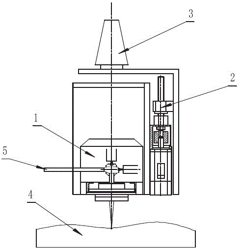
[0014] The invention also provides a laser processing device, which solves the problem that the Z-axis laser focus adjustment function of the existing "3+2-axis" projection processing system must rely on the cooperation of the three-axis machine tool, the processing head is not easy to disassemble and install, and the applicability is not high. , the processing head used in this processing device can be combined with a variety of commercial CNC machine tools for processing. It has the advantages of modular processing unit, easy disassembly and assembly, simple and reliable process, high flexibility, and strong applicability to various curvature complex surface parts.

Method used


Image

  • Laser machining method and device applicable for complicated curved surface

Examples


Embodiment Construction

[0037] Typical implementations of the present invention will be described in detail below with the help of drawings and examples.

[0038] As a method for precisely scanning and processing the surface of parts with complex curved surfaces by using focused laser beams, the invention is applicable to various laser wavelengths, powers, scanning speeds and other technological parameters.

[0039] When implementing the method of the present invention, first analyze the processing requirements, and select a two-axis scanning laser galvanometer that can realize the processing requirements. It is driven by a motor to deflect two X and Y laser plane mirrors to complete the scanning motion, and the scanning focus lens Focus on material processing. Generally, after the size of the laser plane mirror in the laser galvanometer, the motor, the aperture and focal length of the scanning focus lens are determined, parameters such as the scanning range of the galvanometer, the working focal len...


PUM


Abstract

The invention provides a laser machining method applicable for a complicated curved surface. By adopting processing steps of dividing the complicated curved surface into curved surface sheets and establishing a coordinate system of each curved surface sheet, the subsequent processing steps of dividing sub blocks and machining pattern parallel projection can be implemented according to the coordinates of the curved surface sheets respectively, so the limit that a machining molded surface backing to a laser incident direction or a steep surface parallel to an optical axis direction cannot be machined because only one coordinate system is adopted to perform whole injection in the prior art can be overcome, the machining efficiency is improved and the machining applicable range is extended. The invention also provides a laser machining device. The laser machining device has a three-axis laser machining head structure provided with a two-axis laser polarization mirror and a Z-axis mobile mechanism, so the problem that the conventional system depends on a three-axis lathe is solved; therefore, a machining unit is independent and compact, and is easy to assemble and disassemble; the conventional five-axis linkage milling machine can be changed into a laser-etching machining lathe so that the functions are compatible; and the laser machining device has a significant practical value.

Description

technical field [0001] The invention belongs to the application field of laser processing, and in particular relates to a laser processing method and device suitable for secondary precision processing on the surface of complex curved parts. Background technique [0002] In aerospace, automobile, energy, petrochemical, power, military defense and other industries, parts with complex curved surfaces are widely used, such as aircraft wings, marine propellers, engine blades, automotive panel molds, large diesel engine crankshafts, etc. , the shape surfaces are all space complex surfaces. [0003] In order to obtain beautiful, wear-resistant, corrosion-resistant or special electromagnetic properties, secondary precision machining is often required on the surface of complex curved parts, such as etching various texture patterns on the surface of complex curved hard alloy molds, and complex curved surface radar The surface of the insulating substrate is precisely coated with condu...

Claims


Application Information

Patent Timeline
Patent Type & Authority Patents(China)
IPC IPC(8): B23K26/362B23K26/082B23K26/00
Inventor 曹宇曾晓雁段军王泽敏李祥友高明胡乾午刘建国
Owner 武汉飞能达激光技术有限公司
Learn More