Method for accurately finding upper dead point of crank connecting rod pressing machine

A technology of crank connecting rod and press, applied in the direction of press, punching machine, manufacturing tool, etc., can solve the problems of low efficiency, affecting processing accuracy, many human factors, etc., and achieve the effect of simple operation

Active Publication Date: 2011-08-31
NANJING ESTUN AUTOMATION CO LTD
4 Cites 4 Cited by

AI-Extracted Technical Summary

Problems solved by technology

This method is greatly affected by the resolution ability of the human naked eye, and there are many human factors, which often affect ...

Abstract

The invention relates to a method for accurately finding an upper dead point of a crank connecting rod pressing machine. According to a crank connecting rod mechanism principle, the rotation angle of a crank and the movement distance of a slide block are in a nonlinear relation, i.e., the walking distances of the slide block varies when the crank is rotated by the same angle at different positions; and the difference between a current angle of the crank and the upper dead point is resolved according to the relation between the rotation angle increment of the crank and the moving distance increment of the slide block to obtain the position of the upper dead point. The position of the upper dead point of the slide block can be found accurately at the deviation of +/- 1 equivalent angle counting unit without externally connecting special slide block position measuring equipment or changing the original hardware structure. The method is easy and convenient to operate.

Application Domain

Press ram

Technology Topic

Machine pressMeasuring equipment +3

Image

  • Method for accurately finding upper dead point of crank connecting rod pressing machine
  • Method for accurately finding upper dead point of crank connecting rod pressing machine
  • Method for accurately finding upper dead point of crank connecting rod pressing machine

Examples

  • Experimental program(1)

Example Embodiment

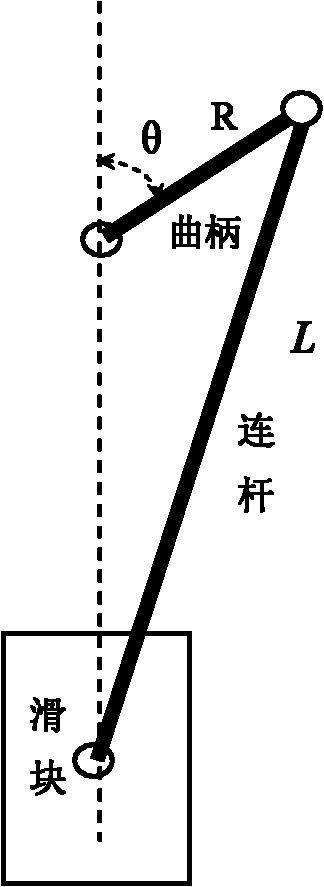
[0018] The application object of the present invention is a crank connecting rod press. The crank connecting rod press controls the rotation of a servo motor or an ordinary AC asynchronous motor, the motor drives the crank, and the eccentric rotation power of the crank is transmitted to the slider through the connecting rod. For the up and down movement of the slider, an angle measuring device is installed on the rotating shaft of the crank, and a fixed slider position measuring device is not installed on the slider side. Such as figure 1 , R is the crank radius, L is the connecting rod length, and θ is the difference between the current crank angle and the top dead center.
[0019] The following components are set on the crank press: motion control components, which control the crank to make arbitrary rotational motion according to the angle; displacement measurement components, which measure the distance difference between the two upward or downward movement of the slider; angle measurement components, which measure the rotation angle of the crank; determine the crank connection The method of the top dead center of the rod press includes the following steps:
[0020] 1) The initial position of the slider ensures that the slider moves in one direction during the subsequent movement, either upwards or downwards. The motion control component controls the crank to rotate at a certain angle to stop. The angle measuring component measures the angle before and after the crank moves. The controller automatically calculates the angle increment Δθ of the crank rotation according to the angle of the crank after the movement and the angle before the movement, and the displacement measuring component measures the moving distance ΔS of the slider at this time;
[0021] 2) Calculate the angle difference θ between the current angle of the crank and the axis of the top dead center based on the crank connecting rod mechanism principle from the angle increment Δθ of the crank rotation and the moving distance increment ΔS of the slider:
[0022] ΔS Δθ = R · sin ( θ ) + R 2 · sin ( 2 θ ) L 2 - R 2 · sin 2 ( θ )
[0023] Among them: R is the crank radius, θ is the difference between the current angle of the crank and the angle at the top dead center position, and L is the length of the connecting rod;
[0024] 3). The crank rotates the angle difference θ in the opposite direction of the rotation direction according to step 1), that is, it reaches the top dead center and stops at the top dead center;
[0025] 4) The top dead center position of the crank connecting rod press is regarded as the 0 angle of the crank.
[0026] As a preferred way, in step 1), first move the slider to near the top dead center, and then control the rotation of the crank by the motion control component.
[0027] The invention can be used for servo crank connecting rod presses or ordinary crank connecting rod presses.
[0028] The following specific examples illustrate the implementation of the present invention. The control program is edited according to the steps of the present invention and installed in the controller of the crank press, and the motion control component, the displacement measurement component, and the angle measurement component are connected to the controller.
[0029] 1) After the crank connecting rod press controller is powered on, enter the manual mode, and manually move the slider up to near the top dead center;
[0030] 2) From the manual mode to the top dead point sub-mode of this mode, such as figure 2 Shown. The current angle display frame 1 is the crank angle before the top dead center is not found, which is any value in the range of 0-360°;
[0031] 3) Place a fixed iron block near the lower surface of the slider with a flat upper surface as a reference plane for measuring the moving distance of the slider;
[0032] 4) Use a vernier caliper to measure the distance s between the lower surface of the slider and the reference plane 1;
[0033] 5) After pressing the "manual down" switch, press the two hands to start the switch, manually let the crank rotate a certain angle downward, the crank drives the slider to move, after the two hands start the switch to release the slider to stop the movement, the crank rotation angle (increase) (Quantity) Display box 2 automatically displays the current crank angle increment Δθ;
[0034] 6) Measure the distance s between the lower surface of the slider and the reference plane again 2;
[0035] 7) Display the movement distance increment ΔS in the slider displacement (increment) box 3, ΔS=s 2 -s 1;
[0036] 8) From the angle increment Δθ of the rotation of the crank and the moving distance increment ΔS of the slider, the angle difference θ between the current crank angle and the top dead center is calculated according to the principle of the crank connecting rod mechanism:
[0037] ΔS Δθ = R · sin ( θ ) + R 2 · sin ( 2 θ ) L 2 - R 2 · sin 2 ( θ )
[0038] Among them: R is the crank radius, θ is the difference between the current angle of the crank and the top dead center, and L is the length of the connecting rod;
[0039] The above formula is edited as a program module for automatic calculation: calculate the top dead center angle 4, start this module for calculation, the controller automatically calculates the difference θ between the current crank angle and the top dead center according to ΔS and Δθ, and calculates the top dead center Angle display frame 5 for display;
[0040] 9) After starting back to the top dead center control 6, press the two-hand start switch, the crank rotates the angle difference θ in the opposite direction according to step 1), reaches the top dead center, and stops at the top dead center;
[0041] 10) The current angle is automatically set to zero after the crank stops at the top dead center: Step 9) The top dead center has been found, and the top dead center position of the crank connecting rod press is taken as the 0 angle of the crank according to the regulations. After the top dead center is found Set the current angle of the crank to 0 so that the position and angle of the crank are consistent.

PUM

no PUM

Description & Claims & Application Information

We can also present the details of the Description, Claims and Application information to help users get a comprehensive understanding of the technical details of the patent, such as background art, summary of invention, brief description of drawings, description of embodiments, and other original content. On the other hand, users can also determine the specific scope of protection of the technology through the list of claims; as well as understand the changes in the life cycle of the technology with the presentation of the patent timeline. Login to view more.

Similar technology patents

Laser radar optical system with optical axis calibrating function and optical axis calibrating method

InactiveCN102353950AOptical axis alignment with high precisioneasy to operate
Owner:INST OF APPLIED ELECTRONICS CHINA ACAD OF ENG PHYSICS +1

Intelligent mobile communication terminal and wireless network access method and system thereof

InactiveCN103068066Aeasy to operateImprove network utilization
Owner:GUANGDONG OPPO MOBILE TELECOMM CORP LTD

Classification and recommendation of technical efficacy words

  • easy to operate

Lancet device

InactiveUS7303573B2inexpensively mass-producedeasy to operate
Owner:ABBOTT DIABETES CARE INC

Rapid and non-invasive optical detection of internal bleeding

InactiveUS20050065436A1easy to operaterapid and accurate result
Owner:HO WINSTON ZONH +2
Why Eureka
Try Eureka