Linear permanent magnetic rail brake

A rail brake, linear technology, applied in the direction of brakes, railway braking systems, railway car body parts, etc. where the braking element interacts with the track, can solve the problem of increasing the gap between the brake and the track, difficult to control the braking force, and reducing the braking force. Braking effect and other issues to avoid demagnetization, ensure safe operation, and reduce magnetic flux leakage

Inactive Publication Date: 2011-08-31
JIANGSU UNIV
View PDF6 Cites 8 Cited by
  • Summary
  • Abstract
  • Description
  • Claims
  • Application Information

AI Technical Summary

Problems solved by technology

The disadvantages of the structure and working method of this kind of permanent magnet rail brake are that the braking force is not easy to control, and the friction is serious at high speed, so that the temperature of the brake is too high, and the permanent magnet is prone to demagnetization; Clearance to track reduces braking effect

Method used


Image

  • Linear permanent magnetic rail brake
  • Linear permanent magnetic rail brake
  • Linear permanent magnetic rail brake

Examples


Embodiment Construction

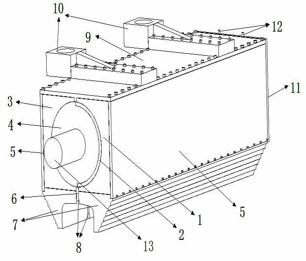
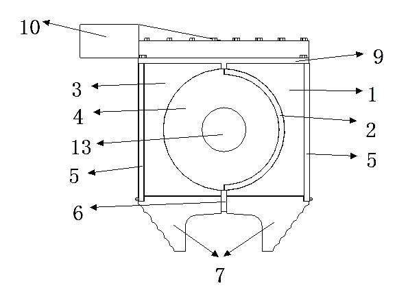
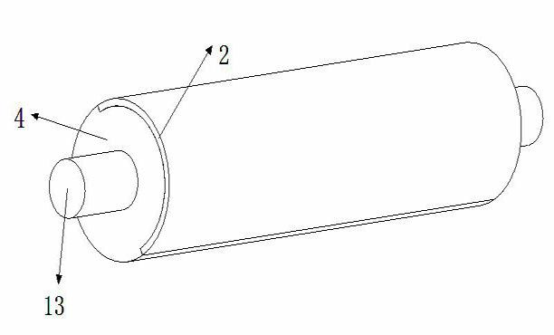
[0017] see Figure 1-3 , the upper part of the present invention is the top cover 9, the two sides of the middle part are the side plates 5, the two ends are the end covers 11, and the lower part is two symmetrical pole shoes 7 which are in symmetrical contact with the track, and the two symmetrical pole shoes 7 The middle of the bottom is fixedly connected to the bottom partition 6, and the bottom partition 6 plays a separating role. A flange 10 is installed on the top cover 9, and the present invention is connected with the train bogie through the flange 10. Install hydraulic cylinder or pneumatic cylinder 12 in end cover 11, install permanent magnet shaft 13 in the middle of two side plates 5, the driving mechanism of hydraulic cylinder or pneumatic cylinder 12 connects permanent magnet shaft 13, drives permanent magnet shaft 13 to rotate, also Axial movement of the permanent magnet shaft 13 can be prevented. The permanent magnet shaft 13 is arranged in the same direction...


PUM


Abstract

The invention discloses a linear permanent magnetic rail brake. A permanent magnetic shaft in the same direction with a pole shoe is arranged between two side plates; a permanet magnet is fixedly sleeved on a permanent magnetic shaft; the permanent magnet is a shaft body composed of two half cylinders with different radiuses; a semi-arc separating plate is fixedly sticked on the surface of the half cylinder with the smaller radius; the semi-arc separating plate is combined with the permanent magnet to form a cylinder; an U-shaped permanent magnet is arranged between the semi-arc separating plate and each side plate; an U-shaped fixing slot is arranged between the half cylinder with the larger radius of the permanent magnet and each side plate; and the S pole or N pole of the U-shaped permanent magnet is arranged corresponding to the N pole or S pole of the permanent magnet. The braking power is controlled through controlling the rotating angle of the permanent magnet shaft, so that the vortex and friction braking manners are realized; the braking distance is reduced; and the braking effect is good.

Description

technical field [0001] The invention relates to a magnetic track brake of a railway train vehicle, which realizes the braking or release of the railway train vehicle through the closing or separation between the magnetic field and the track. Background technique [0002] At present, disc brakes are commonly used on railway passenger vehicles. Although the degree of thermal damage is lower than that of tread brakes, when the train is running at high speed or quasi-high speed, the braking distance must be extended to achieve safety due to the limitation of adhesion conditions. brake. However, if a magnetic rail brake is added to the rail vehicle on the basis of the original braking method, the braking force can be increased, the braking distance can be shortened, and the driving safety of the high-speed rail vehicle can be greatly guaranteed. Magnetic track braking is a new type of braking method developed as the speed of rail vehicles continues to increase. It includes two f...

Claims


Application Information

Patent Timeline
Patent Type & Authority Applications(China)
IPC IPC(8): B61H7/12B61H7/00
Inventor 姚明唐卓华何仁
Owner JIANGSU UNIV
Why Eureka
Try Eureka