Tube connection device

A technology for pipe joints and pipeline connections, applied in the direction of pipes/pipe joints/pipes, fuel injection devices, threaded connections, etc., which can solve problems such as insufficient compression, damage, and large stress.

Inactive Publication Date: 2011-08-31
TI AUTOMOTIVE HEIDELBERG
View PDF0 Cites 6 Cited by
  • Summary
  • Abstract
  • Description
  • Claims
  • Application Information

AI Technical Summary

Problems solved by technology

In the case of pipe joint arrangements known from practice, the more or less uncontrolled screwing in of the connection fitting often leads to excessive stress and dama

Method used


Image

  • Tube connection device
  • Tube connection device
  • Tube connection device

Examples


Embodiment Construction

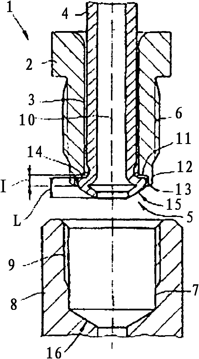
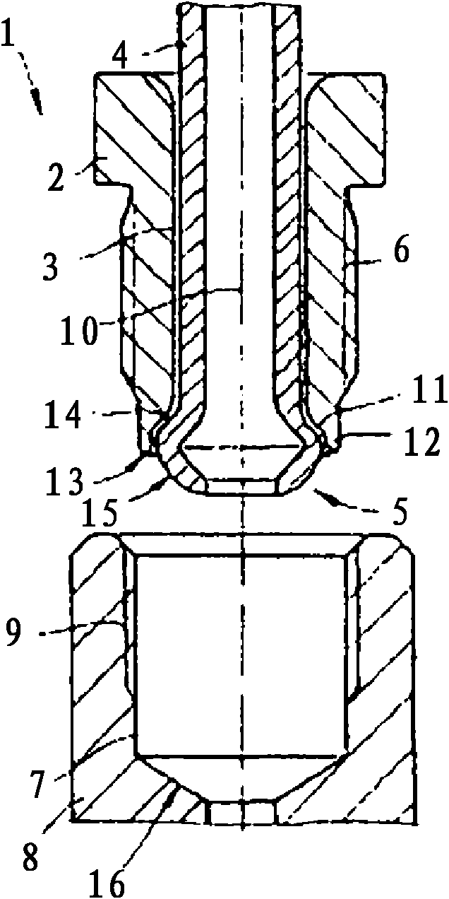
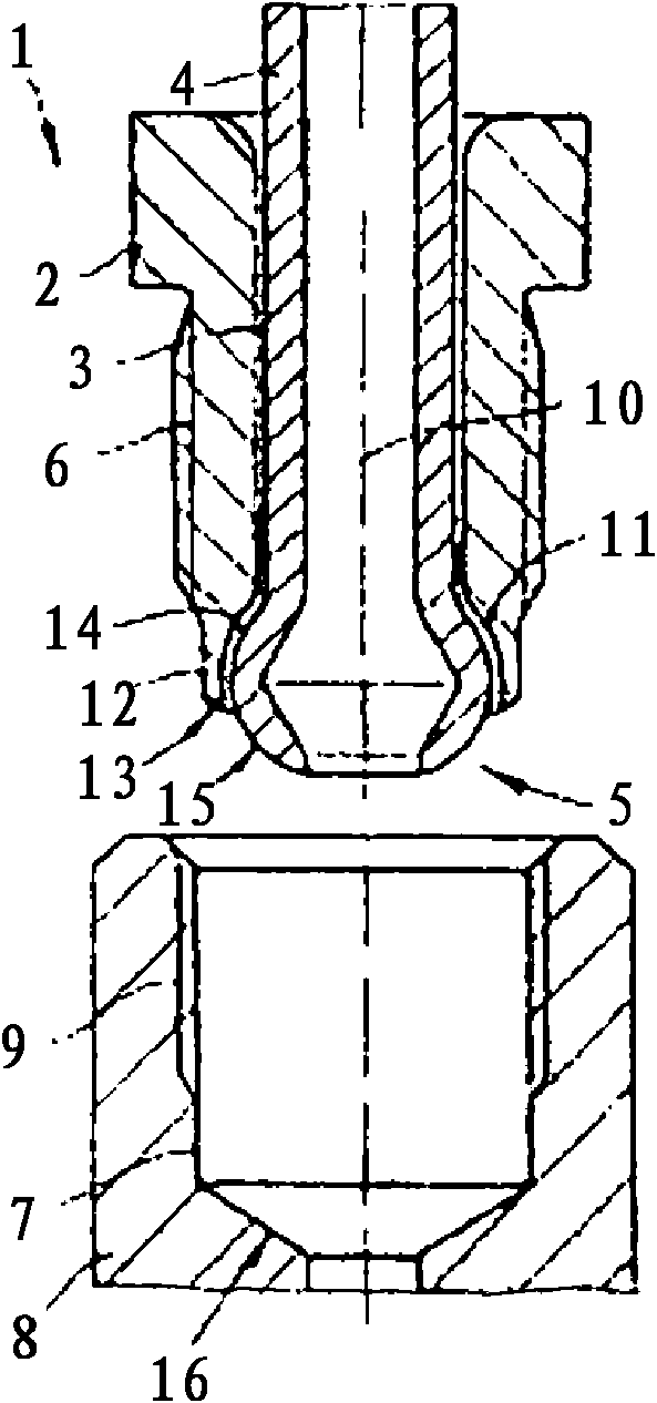
[0037] FIGS. 1 a to 1 c show a pipe connection device 1 with a connection fitting 2 having a receiving channel 3 for a line 4 . In the exemplary embodiment according to FIGS. 1 a to 1 c a line 4 with a flange 5 is arranged in the receiving channel 3 . The connecting fitting 2 here has an external thread 6 which is screwed into a bore 7 of the connecting element 8 with an internal thread 9 . As a result of this screwing in, the connection fitting 2 is moved in the axial direction of the line 4 or the receiving channel 3 or along their longitudinal axis 10 .

[0038] According to the exemplary embodiment shown in FIGS. 1a to 1c, the connection fitting 2 has a front pressing surface 11 from which an annular stop element 12 protrudes and which is formed by the front pressing surface 11. The ring stop element 12 surrounds it. According to FIGS. 1 a to 1 c , the annular stop element 12 has a front contact surface 13 which is of conical configuration. 1a to 1c, it can be seen that...


PUM


Abstract

A pipe connection arrangement for the connection of pipelines, in particular of motor vehicle pipelines to a connection element, wherein a connection fitting is provided which encompasses the pipeline to be connected in the region of one of its pipeline ends and which, with a front side press surface of a of a rear side surface facing a flange connected to the pipeline end. The flange exhibits a sealing surface on its front side, wherein the sealing surface can be pressed by means of an axial movement of the connection fitting to a contact surface of the connection element or to a second sealing surface of a second flange of a second pipeline, wherein a stop element is arranged between the contact fitting and contact surface of the connection element and wherein this stop element limits or interrupts the axial movement of the connection fitting.

Description

technical field [0001] The invention relates to a pipe coupling device for connecting a line, in particular a motor vehicle line, to a connecting element. Background technique [0002] Pipe joint arrangements of the type described above are basically well known in practice. During handling, the flange molded onto the pipeline is pressed against the connecting surface of the connecting element. The clamping pressure required for this is exerted by means of the connection fitting, which is screwed into the connection element and lies flat against the rear side of the flange. In the case of pipe fittings known from practice, the more or less uncontrolled screwing in of the connection fitting often leads to excessive stress and damage to the flanges against which the connection fitting is pressed. And it also leads to insufficient compaction. Often, this results in undesired leakage or material damage. Contents of the invention [0003] The invention is therefore based pre...

Claims


Application Information

Patent Timeline
IPC IPC(8): F16L15/04
CPCF16L19/0286F16L19/0225F16L19/0283F02M55/005F16L19/02F16L19/04F16L19/05F16L21/08
Inventor G·韦克W·赫泽尔U·菲德勒S·阿博特
Owner TI AUTOMOTIVE HEIDELBERG
Why Eureka
Try Eureka