Medium-voltage integrated intelligent circuit breaker

A technology of circuit breakers and vacuum circuit breakers, applied in the direction of high-voltage air circuit breakers, circuits, high-voltage/high-current switches, etc.

Inactive Publication Date: 2011-08-31
SOUTHEAST UNIV
View PDF9 Cites 9 Cited by
  • Summary
  • Abstract
  • Description
  • Claims
  • Application Information

AI Technical Summary

Problems solved by technology

Since the complete set of intelligent medium-voltage switchgear uses multiple components to realize the function, and a single component is manufactured by different manufacturers, the matching of the system often cannot reach the best state, and the coordination and reliability of the product is poor.
Moreover, the volume of the equipment is large, the material consumption is high, the workload of manufacturing, commissioning and operation, maintenance and repair is large, and the technical requirements are high.
In addition, the internal parameters of the circuit breaker are difficult to obtain, and it is difficult to judge the remaining service life of the switchgear and calculate the maintenance period

Method used


Image

  • Medium-voltage integrated intelligent circuit breaker
  • Medium-voltage integrated intelligent circuit breaker
  • Medium-voltage integrated intelligent circuit breaker

Examples


Embodiment Construction

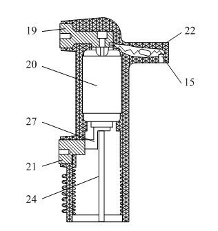
[0017] A medium-voltage intelligent vacuum circuit breaker, comprising a solid-sealed vacuum pole 13 and a circuit breaker frame 18, one side of the solid-sealed vacuum pole 13 is provided with an upper contact arm 11 and a lower contact arm 16, and the upper part of the other side is provided with a Vacuum pole pillar 22, the vacuum pole pillar 22 is connected to the upper part of the circuit breaker frame 18 through the pillar bolt 15, the lower end of the sealed vacuum pole 13 is connected to the base of the circuit breaker frame 18; the upper end of the solid-sealed vacuum pole 13 adopts An upper contact arm connection conductor 19 is embedded in epoxy resin, the lower end of the upper contact arm connection conductor 19 is connected to the vacuum interrupter 20, and a lower contact arm connection conductor 21 is provided on the lower side of the embedded vacuum pole 13. The connecting conductor 21 of the lower contact arm is connected to the vacuum interrupter 20 through t...


PUM


Abstract

One side of a solid-sealed vacuum polar pole is provided with an upper contact arm and a lower contact arm, the upper part of the other side of the solid-sealed vacuum polar pole is provided with a vacuum polar pole column, the column is connected with the upper part of a circuit breaker framework through a column bolt, the lower end of the solid-sealed vacuum polar pole is connected with a base of the circuit breaker framework; an upper contact arm connecting conductor is fixedly sealed at the upper end of the solid-sealed vacuum polar pole, a vacuum extinction chamber is connected to the lower end of the upper contact arm connecting conductor, one side of the lower part of the fixedly sealed vacuum polar pole is provided with a lower contact arm connecting conductor connected with the vacuum extinction chamber, the lower end of the vacuum extinction chamber is provided with a connecting rod I; an electronic voltage transformer is fixedly sealed in the vacuum polar pole column; and an electronic current transformer is sleeved on the upper contact arm and fixedly sealed with the upper contact arm into a whole. A permanent magnet operating mechanism and an intelligent unit are arranged in the circuit breaker framework, a connecting rod II at the lower end of the permanent magnet operating mechanism is connected with the connecting rod I through a connecting rod III; and the intelligent unit is respectively connected with the electronic current transformer, the electronic voltage transformer and the permanent magnet operating mechanism through control wires.

Description

technical field [0001] The invention belongs to the technical field of smart grids, and in particular relates to a medium-voltage smart circuit breaker. Background technique [0002] Smart grid is the wind vane of the development and transformation of the world's power system, and an important trend of power technology innovation and development in the 21st century. In fact, the smart grid is to improve the whole system of power transmission and distribution to a higher level. Through the concept of smart grid, the operation of our power grid is more reliable, safer and more continuous. The smart grid requires the entire power grid from power generation, power transmission to power distribution, including systems and components that are reliable and safe, and can guarantee the continuity and safety of power supply, which also puts forward higher requirements for the switchgear industry. [0003] Industrialized countries, including the United States, are gathering the streng...

Claims


Application Information

Patent Timeline
Patent Type & Authority Applications(China)
IPC IPC(8): H01H33/66
Inventor 张建忠程明张良锁蔡长虹
Owner SOUTHEAST UNIV
Why Eureka
Try Eureka