

Cell stack of fuel cells and method for fastening cell stack of fuel cells
A fuel cell and cell stack technology, which is applied in the field of fuel cell stacks and the fastening of fuel cell stacks, can solve the problems of increasing the size of fuel cells, and achieve the effects of no damage to performance and miniaturized surface area.
- Summary
- Abstract
- Description
- Claims
- Application Information
AI Technical Summary
Problems solved by technology
Method used
Image

Examples
Embodiment approach 1
[0053] [Structure of cell stack of fuel cell]
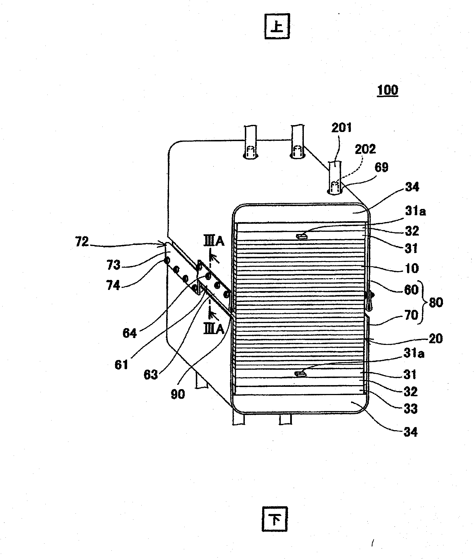
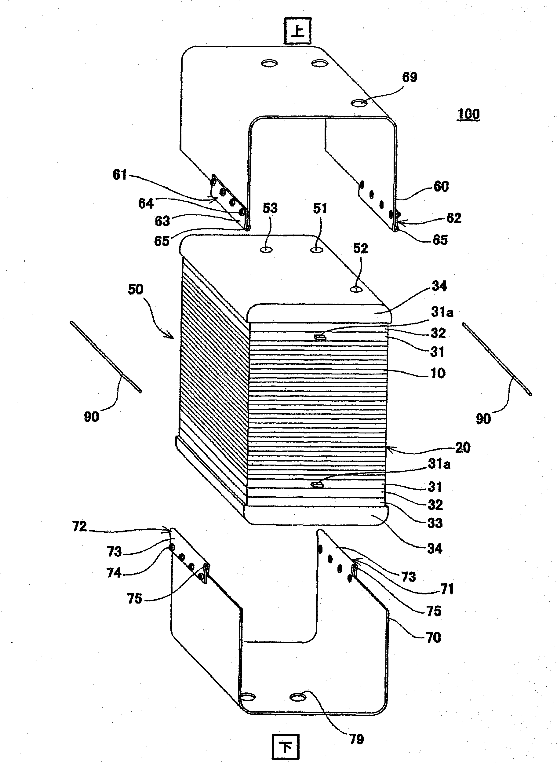
[0054] figure 1 is a perspective view schematically showing a schematic structure of a fuel cell stack according to Embodiment 1 of the present invention, figure 2 will be figure 1 An exploded schematic view of the cell stack of the fuel cell shown. In addition, in figure 1 and figure 2 In , the up-down direction in the cell stack of the fuel cell is represented as the up-down direction in the figure.
[0055] Such as figure 1 and figure 2 As shown, the fuel cell stack 100 according to Embodiment 1 of the present invention includes a cuboid stack body 50 , a U-shaped first band member 60 and a U-shaped second band member 70 for fastening. Belt 80 and a pair of dowel pins 90,90. The first belt member 60 and the second belt member 70 are arranged to cover the upper surface (upper end surface), lower surface (lower end surface) and a pair of opposite side surfaces of the battery stack body 50 and extend around the battery...
Embodiment approach 2
[0099] Figure 5 It is a perspective view schematically showing a schematic structure of a fuel cell stack according to Embodiment 2 of the present invention. Figure 6 will be Figure 5 Schematic diagram of an exploded cell stack for the fuel cell shown. In addition, in Figure 5 and Figure 6 In , the up-down direction in the cell stack of the fuel cell is represented as the up-down direction in the figure.
[0100] Such as Figure 5 and Figure 6 As shown, the fuel cell stack 100 according to the second embodiment of the present invention has the same basic structure as the fuel cell stack 100 according to the first embodiment. The structure of the component joint 72 is different.
[0101] Specifically, in the fuel cell stack 100 according to Embodiment 2, the elastic member 33 is formed of a compression spring. Moreover, the 1st belt member joining part 61 - the 4th belt member joining part 72 have a plurality (here, seven pieces) of joining units 66, 76 formed in ...
Embodiment approach 3
[0105] Figure 7 It is a perspective view schematically showing a schematic structure of a fuel cell stack according to Embodiment 3 of the present invention. Figure 8 It is a pattern that expresses the composition Figure 7 It is a perspective view showing a schematic structure of a first belt member and a second belt member of a cell stack of the fuel cell shown. In addition, in Figure 7 In the figure, the up-down direction in the cell stack of the fuel cell is represented as the up-down direction in the figure, and in Figure 8 , the vertical direction among the first belt member and the second belt member is shown as the vertical direction in the figure.
[0106] Such as Figure 7 and Figure 8 As shown, the fuel cell stack 100 according to Embodiment 3 of the present invention has the same basic structure as the fuel cell stack 100 according to Embodiment 1. 72 is different in that it is not constituted by the joining forming portions 63 and 73 but is constituted ...
PUM
 Abstract
Description
Claims
Application Information