
Automatic stamping device

An automatic and stamping technology, applied in printing, stamping, etc., can solve the problems of high error rate and low work efficiency, and achieve the effect of reducing error rate, reducing labor intensity, and improving the automation process

Inactive Publication Date: 2011-09-07
YUNNAN NANTIAN ELECTRONICS INFORMATION CORP +1
View PDF3 Cites 6 Cited by
  • Summary
  • Abstract
  • Description
  • Claims
  • Application Information

AI Technical Summary

Problems solved by technology

[0004] In order to solve the problems of low work efficiency and high error rate caused by manual stamping of existing bank bills, the present invention provides an automatic stamping device

Method used


Image

  • Automatic stamping device
  • Automatic stamping device

Examples


Embodiment Construction

[0013] The present invention will be further described below in conjunction with the accompanying drawings.

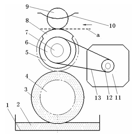
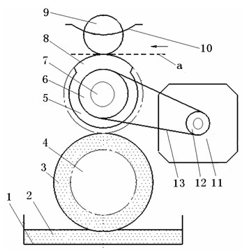
[0014] The automatic stamping device provided by the present invention comprises a seal roller 5 with an arc-shaped raised stamp 8 on it, a driving assembly connected to the stamp roller 5, a floating pinch roller group and an ink roller group matched with the stamp roller 5 , and form the channel of bill a between the stamp roller 5 and the floating pinch roller group, the drive assembly includes a drive wheel 6 arranged on the stamp roller 5 roller shaft 7, the drive wheel 6 passes through a transmission belt 13 and a motor 11 shaft The driving wheel 12 on the top is connected so that under the drive of the motor 11, the roller shaft 7 of the stamp roller 5 is rotated by the driving wheel 12, the transmission belt 13 and the transmission wheel 6 on the motor shaft, and then the stamp roller 5 is driven to rotate, and the stamping is completed And go up new oil, descr...


PUM


Abstract

The invention provides an automatic stamping device, which is characterized by comprising a stamp roller which is provided with a protruding stamp, a driving component connected with the stamp roller, a floating compression roller set and a stamp pad ink roller set which are respectively matched with the stamp roller, and a bill channel formed between the stamp roller and the floating compression roller set. The automatic stamping device can automatically stamp various bills easily in a mechanical stamping mode instead of a manual stamping mode, reduces the labor intensity of workers, improves work efficiency of stamping the bills, and reduces the error rate; the automatic stamping device can be matched with other bill processing devices such as a printer and a conveyer to realize a series of automatic bill processing actions such as printing, conveying, stamping and the like, improves the bill processing speed of a bank system, accelerates the automation process of processing the bills, and has the advantages of simple structure, convenience of use, good stamping effect, convenience of overhaul and maintenance, high automation degree and the like.

Description

[0001] technical field [0002] The invention relates to a device, in particular to an automatic stamping device, which belongs to the technical field of design and manufacture of automatic stationery equipment. Background technique [0003] With the continuous development of our country's economy, the bank's corporate business is becoming more and more heavy. At present, electronic receipts are used as proof of payment for public business operations. Due to the massive increase in the bank's corporate business, the bank prints a huge number of electronic receipts every day, and each electronic receipt requires the staff to affix the bank's business seal before returning it to the customer. Therefore, the daily workload of bank staff is very huge, which not only consumes a lot of working time and affects work efficiency, but also is prone to errors by manual operation, which brings unnecessary troubles to customers and the bank itself. Therefore it is necessary to improve ...

Claims


Application Information

Patent Timeline
Patent Type & Authority Applications(China)
IPC IPC(8): B41K3/26B41K3/54
Inventor 桂俊德马竹仙李成
Owner YUNNAN NANTIAN ELECTRONICS INFORMATION CORP
Learn More