Fitting structure of guide rail and furnace body of metal round bar heating furnace

A matching structure and heating furnace technology, which is applied in the field of industrial kilns, can solve the problems of slow heating speed, high labor intensity, and increasing the area occupied by the heating furnace, so as to ensure uniform heating, reduce work intensity, and improve heating effect. Effect

Inactive Publication Date: 2011-09-07
CHANGSHU FEIFAN METALWORK
View PDF7 Cites 23 Cited by
  • Summary
  • Abstract
  • Description
  • Claims
  • Application Information

AI Technical Summary

Problems solved by technology

[0004] The hearth structure of the above-mentioned heating furnace has at least the following two deficiencies: one is that the bar is in contact with the bottom wall of the furnace as a whole, so the contact area is large, which affects the heating effect of the bar, and the specific performance is that the heating speed is slow
In order to make up for this deficiency, the length of the heating furnace is usually extended appropriately so that the bar can obtain effective heating time and reach the heating temperature. Reaching about 1100°C guarantees the subsequent rolling process requirements, while the above-mentioned loss is a waste of energy, increased production costs, and increased floor space of the heating furnace, etc.; The inclination rolls autonomously, so it is easy to produce piles that affect heating, and even stagnate due to piles. In this case, workers usually use the observation holes on the wall (sid

Method used


Image

  • Fitting structure of guide rail and furnace body of metal round bar heating furnace
  • Fitting structure of guide rail and furnace body of metal round bar heating furnace
  • Fitting structure of guide rail and furnace body of metal round bar heating furnace

Examples


Embodiment Construction

[0022] In order to enable examiners of the Patent Office, especially the public, to more clearly understand the technical essence and beneficial effects of the present invention, the applicant will describe in detail in the form of examples below, but the description of the examples is not intended to describe the solution of the present invention. As a limitation, any equivalent transformations made according to the concept of the present invention that are merely formal rather than substantive should be regarded as the technical solution scope of the present invention.

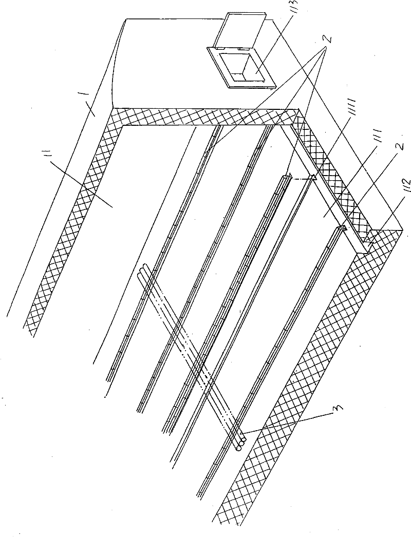
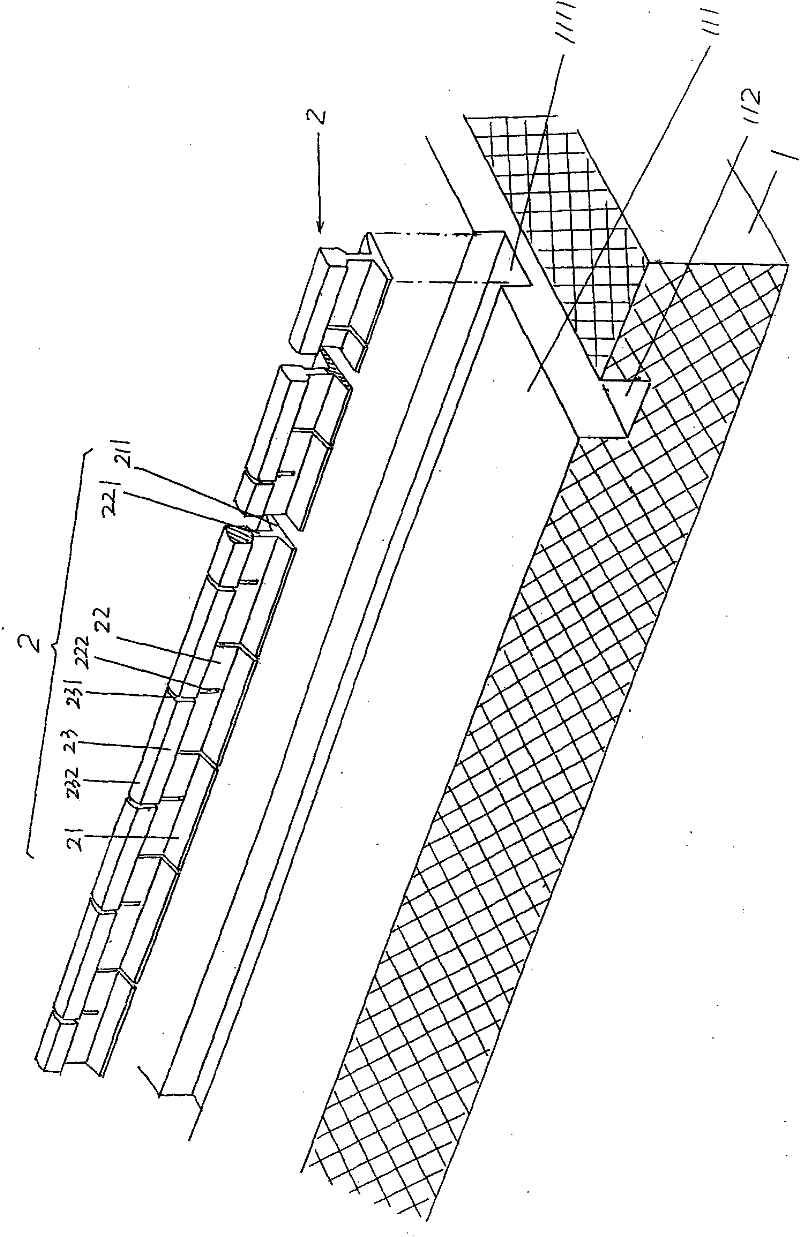
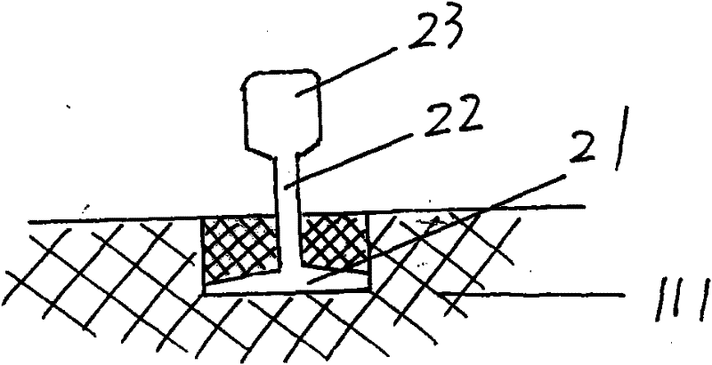
[0023] Please see figure 1 , figure 2 with image 3 , Because the metal round bar heating furnace is a well-known technology, the applicant is figure 1 with figure 2 Only a part of the furnace body 1 is shown in figure 1 with figure 2 The position shown is an example, the left end is the feed port, and the right end is the discharge port.

[0024] As the technical point of the technical solution provided by th...


PUM


Abstract

The invention relates to a fitting structure of a guide rail and a furnace body of a metal round bar heating furnace, belonging to the technical field of industrial kiln furnaces. The metal round bar heating furnace comprises the furnace body which is provided with a hearth. The fitting structure is characterized in that the hearth bottom wall of the hearth is provided with guide rail grooves at intervals; the guide rail grooves are in parallel with the length direction of the hearth; the guide rail is arranged in each guide rail groove; the guide rail comprises a guide rail seat, a connecting plate and a guiding bar which are mutually integrated into a structure; the guide rail seat is positioned at the bottom part of the connecting plate and is embedded with the guide rail grooves; the guiding bar is positioned at the top part of the connecting plate; the guide rail seat is provided with guide rail seat expansion grooves at intervals; the connecting plate is provided with first connecting plate expansion grooves at intervals; the first connecting plate expansion grooves are communicated with the guide rail seat expansion grooves; the guiding bar is provided with guiding bar expansion grooves at intervals; and the guiding bar expansion grooves and the first connecting plate expansion grooves are formed at intervals. The structure has the advantages that the heating efficiency is improved, energy sources are saved, uniform heating can be ensured, and the working intensity is relieved.

Description

Technical field [0001] The invention belongs to the technical field of industrial kilns, and specifically relates to a matching structure of a guide rail and a furnace body of a metal round bar heating furnace. Background technique [0002] In the process of manufacturing metal products by hot rolling, the metal material is fed from the feeding port (also called the feeding port or feeding port) at one end of the heating furnace, and after passing through the furnace, it is led out from the discharge port at the other end of the heating furnace. Rolled into the required products by corresponding hot rolling equipment. Now take the manufacture of steel balls as grinding media as an example. First, a metal round bar is introduced from the feed opening at one end of the heating furnace. After passing through the furnace heating zone, the heated metal round bar is output from the discharge opening, and then rolled by the ball It is rolled into a ball, then quenched, and finally anne...

Claims


Application Information

Patent Timeline
IPC IPC(8): F27D3/00
Inventor 陈刚
Owner CHANGSHU FEIFAN METALWORK
Why Eureka
Try Eureka