
Method and system for measuring noise frequency response function

A technology of frequency response function and measurement method, which is applied to vibration measurement in solids, measurement vibration, and measurement devices, etc., can solve the problems of inability to test the noise characteristics of parts alone, cumbersome insertion loss test methods, and complicated operations, etc., to achieve test The method is reasonable and simple, the development cycle is shortened, and the equipment structure is simple

Active Publication Date: 2011-09-07
CHERY AUTOMOBILE CO LTD
View PDF2 Cites 14 Cited by
  • Summary
  • Abstract
  • Description
  • Claims
  • Application Information

AI Technical Summary

Problems solved by technology

[0005] The purpose of the present invention is to provide a noise frequency response function measurement method and measurement system, to solve the high cost and complicated operation of the current transmission loss test method, and to solve the cumbersome insertion loss test method, and the insertion loss cannot be tested separately The problem with noise characteristics

Method used


Image

  • Method and system for measuring noise frequency response function
  • Method and system for measuring noise frequency response function
  • Method and system for measuring noise frequency response function

Examples


Embodiment 1

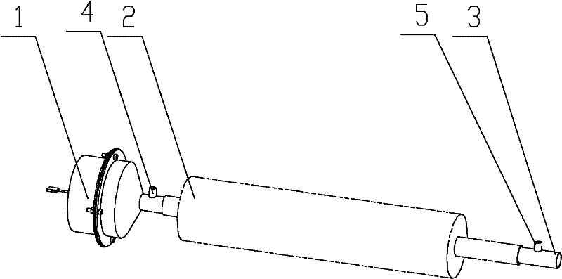
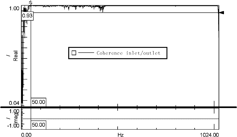
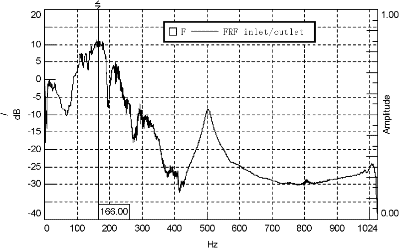
[0021] Embodiment 1: is a kind of such as figure 1 The measurement method and measurement process of the measurement system of the noise frequency response function are shown. The present invention proposes a new test method, which measures the sound pressure at the inlet and outlet of the tested part, and performs a ratio operation on the sound pressure to obtain the frequency response function curve of the tested part. From the frequency response function curve, it can be seen that the measured part noise characteristics. This embodiment uses the following equipment: noise data acquisition system, microphone for measuring noise signals, notebook or other computers with noise software installed, power amplifier, excitation sound source, tailpipe. The noise software used in this embodiment is conventional noise software provided by Chery Automobile Co., Ltd., and its software name is RFR test.9A. The output of the noise data acquisition system is connected to the input of th...


PUM


Abstract

The invention discloses a method and system for measuring a noise frequency response function. The method is used for testing the sound pressures at the inlet and outlet of a tested part and performing the ratio operation on the sound pressures so as to acquire a frequency response function curve of the tested part, thereby showing the noise feature of the tested part based on the frequency response function curve. The measuring system comprises the tested part, a measuring device used for measuring noise signals, a noise signal source and a tail pipe, wherein the noise signal source and the tail pipe are respectively arranged at two ends of the tested part; the measuring device used for measuring the noise signals comprises a first microphone arranged at the outlet of the noise signal source and a second microphone arranged on the tail pipe; and the output signals of the first and second microphones are connected to a noise data processing system. The measuring method provided by the invention is reasonable, simple and convenient, and high in measuring efficiency. The measurement in an anechoic chamber is not required, the demand on the external environment is lower, and the experimental cost is low. The adopted device is simple in structure and convenient to operate. The development period of parts can be shortened and the development cost can be saved. The method and system provided by the invention are suitable for noise measurement on parts of air-intake exhaust systems of various cars.

Description

technical field [0001] The invention relates to a noise measurement system and a measurement method, in particular to a noise frequency response function measurement system and method for automobile intake and exhaust system components. Background technique [0002] With consumers' requirements for driving comfort, major automobile companies are paying more and more attention to the NVH (Noise, Vibration, Harshness) performance of automobiles. In the noise of the whole vehicle, the biggest noise contribution comes from the intake and exhaust system of the car engine at low and medium speeds. [0003] At present, the noise evaluation for the intake and exhaust system or parts of automobiles is generally by testing the transmission loss or insertion loss of the system or parts. The transmission loss can evaluate the noise reduction effect of a single noise reduction element, and can analyze the noise reduction effect of the noise reduction element at each frequency. If it is ...

Claims


Application Information

Patent Timeline
Patent Type & Authority Applications(China)
IPC IPC(8): G01H1/00
Inventor 常辉邓晓龙陈晋阁张爱东
Owner CHERY AUTOMOBILE CO LTD
Learn More