Detecting device for detecting lateral pressure of great-mobility concrete template

A concrete formwork and testing device technology, applied in the direction of measuring fluid pressure, measuring devices, material inspection products, etc., can solve the problems of inaccurate measurement results, large amount of concrete, limited pouring height, etc., and achieve reliable work, easy operation, and measurement fast results

Inactive Publication Date: 2011-09-07
HARBIN INST OF TECH
View PDF4 Cites 17 Cited by
  • Summary
  • Abstract
  • Description
  • Claims
  • Application Information

AI Technical Summary

Problems solved by technology

[0004] The purpose of the present invention is to solve the problem of inaccurate measurement results caused by large mold size, large amount of concrete, and limited pouring height of the test by using manometer and electronic pressure sensor to measure the side pressure of concrete formwork in the existing laboratory. A test device for detecting side pressure of high fluidity concrete formwork

Method used


Image

  • Detecting device for detecting lateral pressure of great-mobility concrete template
  • Detecting device for detecting lateral pressure of great-mobility concrete template

Examples


specific Embodiment approach 1

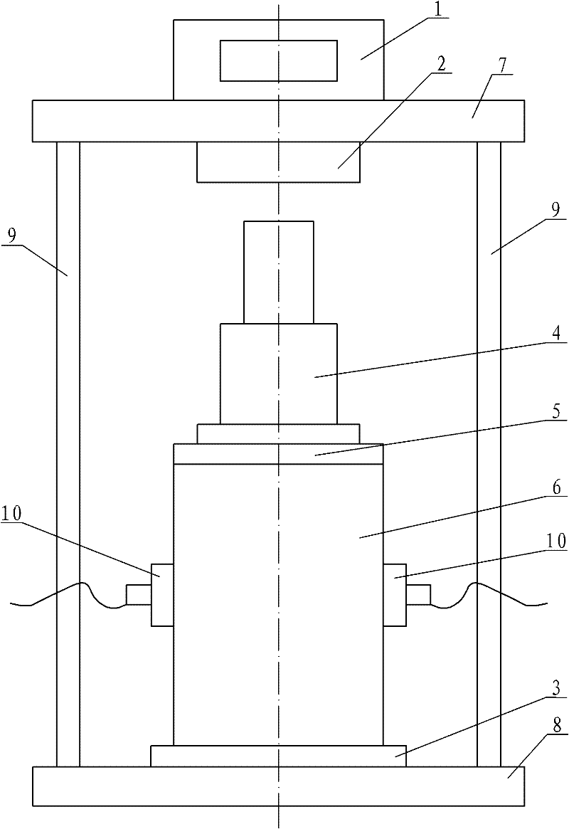
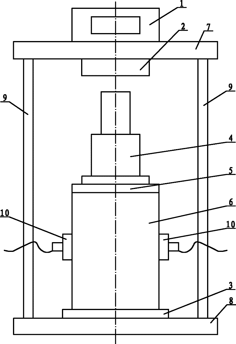
[0008] Specific implementation mode one: combine figure 1 Describe this embodiment, this embodiment includes a data acquisition and display instrument 1, a pressure sensor 2, a steel cylinder chassis 3, a screw jack 4, a steel cylinder sealing piston 5, a circular steel cylinder 6, an upper plate 7, a lower plate 8, two The pillar 9 and the two pressure sensors 10, the upper plate 7 and the lower plate 8 are arranged up and down, and the two pillars 9 are symmetrically arranged between the upper plate 7 and the lower plate 8 relative to the center line of the upper plate 7 and the lower plate 8, and The two pillars 9 are fixedly connected to the corresponding upper plate 7 and the lower plate 8 respectively, the steel cylinder chassis 3 is arranged on the upper end surface of the lower plate 8, and the steel cylinder chassis 3 is fixedly connected to the lower plate 8, and the circular steel cylinder 6 is arranged on the On the upper end surface of the steel cylinder chassis 3...

specific Embodiment approach 2

[0009] Specific implementation mode two: combination figure 1 To describe this embodiment, the vertical centerline of the pressure sensor 2 , the vertical centerline of the screw jack 4 and the vertical centerline of the circular steel cylinder 6 in this embodiment are on the same straight line. This design can ensure accurate test results. Other components and connections are the same as those in the first embodiment.

specific Embodiment approach 3

[0010] Specific implementation mode three: combination figure 1 The present embodiment will be described. In this embodiment, the diameter of the inner cavity of the circular steel cylinder 6 is 200 mm, and the height of the circular steel cylinder 6 is 400 mm. When the circular steel cylinder 6 is the above value, it is the best value for quickly and accurately measuring the side pressure of the large fluidity concrete formwork. Other components and connections are the same as those in the first embodiment.

[0011] Working process of the present invention:

[0012] 1), check whether the connection between the circular steel cylinder 6 and the steel cylinder chassis 3, and the two pressure sensors 10 and the circular steel cylinder 6 is tight, so as to ensure that the circular steel cylinder 6 does not leak;

[0013] 2), put the mixed concrete into the circular steel cylinder 6 in two layers, and manually vibrate to make the concrete dense, and then cover the steel cylinder...


PUM

PropertyMeasurementUnit
diameteraaaaaaaaaa
heightaaaaaaaaaa

Abstract

The invention provides a detecting device for detecting lateral pressure of a great-mobility concrete template and relates to a detecting device for detecting the lateral pressure of a concrete template, in order to solve the problems, such as large mould size, large concrete consumption, limited detection height and inaccurate measurement result existing in the traditional lateral pressure laboratory detection of a concrete template. An upper plate of the detecting device is exactly arranged on an lower plate of the detecting device, wherein two struts are arranged between the upper plate and the lower plate; a steel cylinder chassis is arranged on the upper end face of the lower plate; a round steel cylinder is arranged on the upper end face of the steel cylinder chassis; a steel cylinder sealing piston is arranged in the round steel cylinder and at the upper end; a screw jack is arranged on the upper end face of the steel cylinder sealing piston; a pressure sensor is fixed on the lower end face of the lower plate; a data acquisition display instrument is arranged on the upper end face of the upper plate; two pressure transducers are symmetrically arranged on the side wall of the round steel cylinder; the diameter of the inner cavity of the round steel cylinder is 200mm; and the height of the round steel cylinder is 400mm. The detecting device is used for detecting the lateral pressure of the great-mobility concrete template.

Description

technical field [0001] The invention relates to a test device for the lateral pressure of a concrete formwork. Background technique [0002] With the rapid development of civil engineering materials and construction technology, high-fluidity concrete that can be used for pumping or self-compacting (vibration-free) construction has become an important development direction of modern concrete. The main advantages of high-fluidity concrete are: the height of one-time pouring is large, the pouring period is shortened, the construction progress is accelerated, and the adverse effects of manual operations on concrete properties (such as air content) can be reduced or avoided, ensuring uniformity and durability of concrete sex. The traditional view is that due to its high fluidity, the hydrostatic pressure generated by high-fluidity concrete is all applied to the formwork, so more ribbed or heavier molds are often used, which greatly increases the construction cost. At the same t...

Claims


Application Information

Patent Timeline
Patent Type & Authority Applications(China)
IPC IPC(8): G01L11/00G01N33/38
Inventor 高小建王子龙邓宏卫杨英姿
Owner HARBIN INST OF TECH
Why Eureka
Try Eureka