

Cavitation erosion test equipment for testing material performance and test method thereof
A cavitation cavitation erosion and material performance technology, applied in the analysis of materials, instruments, etc., can solve problems such as difficult operation and maintenance, complex test process, and insufficient simulation level, and achieve stable cavitation cavitation test performance and simple process operation , the effect of a small number of working parts
Inactive Publication Date: 2011-09-07
DALIAN MARITIME UNIVERSITY
View PDF5 Cites 19 Cited by
- Summary
- Abstract
- Description
- Claims
- Application Information
AI Technical Summary
Problems solved by technology
The research on cavitation and cavitation erosion performance evaluation of materials is mainly based on indoor experiments. The research on existing cavitation and cavitation equipment shows that the common problem of this type of equipment is the cavitation and cavit
Method used
View moreImage
Smart ImageViewing Examples

Examples
 PUM
 Abstract
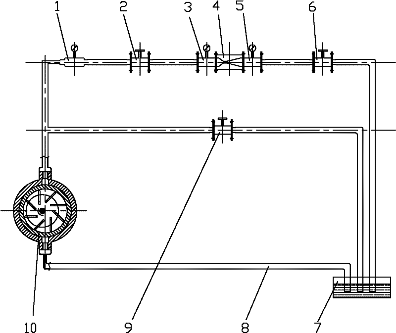
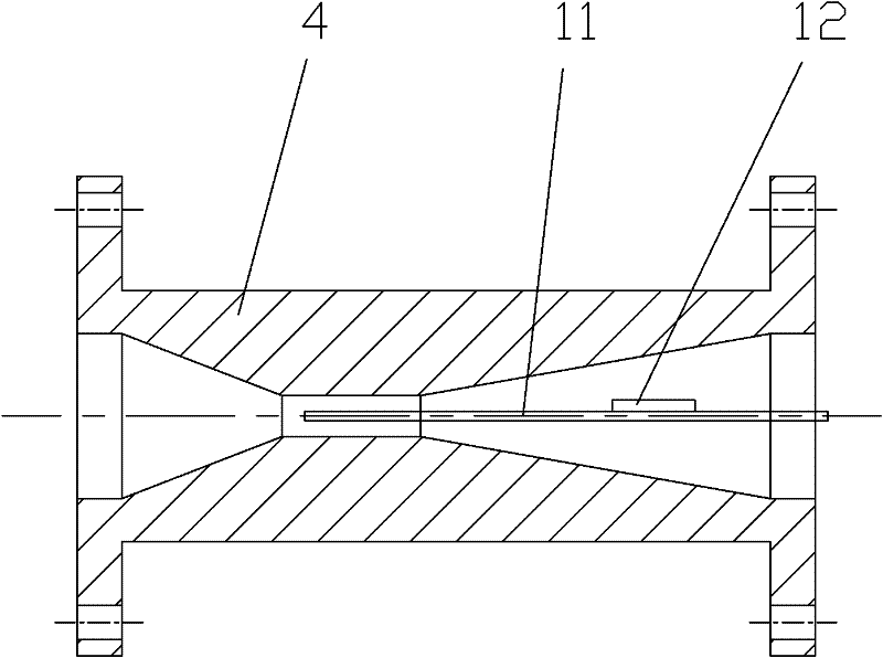
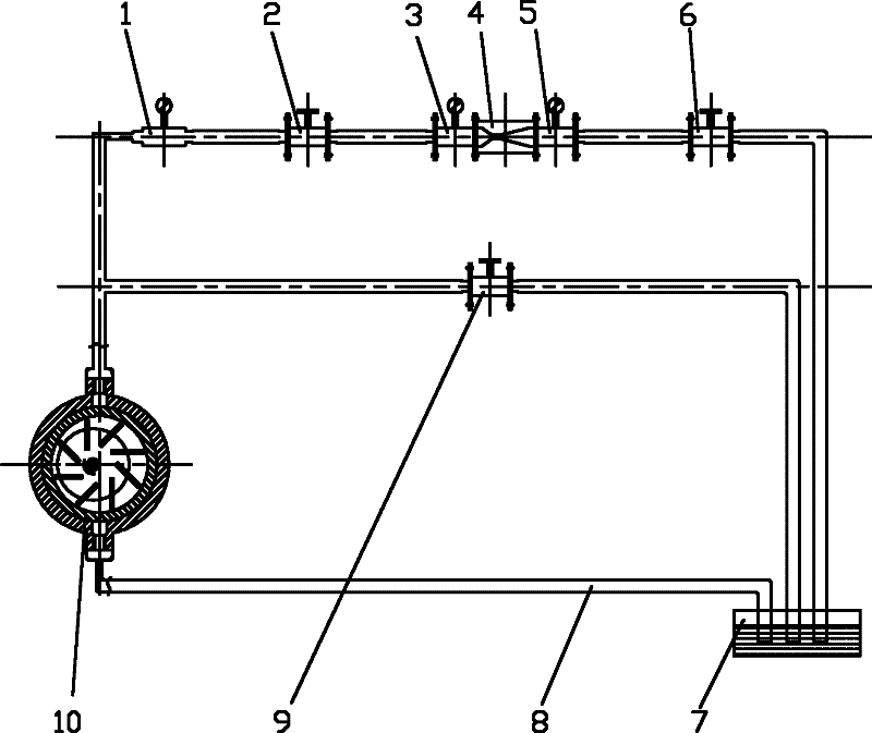
The invention discloses cavitation erosion test equipment for testing material performance and a test method thereof, wherein the equipment comprises a Venturi tube, a water tank, a centrifugal pump, a pipe system, a pressure meter A, a pressure meter B, a flow meter, a flow regulation valve A, a flow regulation valve B and a flow regulation valve C, wherein the front end of the Venturi tube is respectively connected with the pressure meter A, the flow regulation valve A, the flow meter, the centrifugal pump and the water tank through the pipe system in sequence; and the rear end of the Venturi tube is respectively connected with the pressure meter B, the flow regulation valve B and the water tank through the pipe system in sequence. The flow regulation valve A and the flow regulation valve B are regulated so that an inlet end and an outlet end of the Venturi tube has a certain pressure difference, and cavitation phenomena occur at the tail end of the neck part of the Venturi tube and the front part of an outlet taper angle. The test method is closer to the generating process of the cavitation erosion in fluid under the actual working conditions. The equipment disclosed by the invention needs few workpieces and has low cost, simple operation process and stable performance in the cavitation test.
Description
Technical field [0001] The invention relates to a material performance test technology, in particular to a cavitation cavitation test equipment and a test method for testing the material performance. Background technique [0002] Cavitation and cavitation are a microscopic, instantaneous, random, and multiphase complex process. They are also one of the main causes of damage to hydraulic machinery, involving instantaneous gas-liquid phase transitions, energy transfer, and material response. Cavitation and cavitation involve many fields, such as aerospace, national defense, navigation, chemical industry, atomic energy, biology and medicine. Therefore, studying the occurrence mechanism of cavitation and cavitation phenomenon and the technical methods to suppress cavitation not only have far-reaching theoretical significance, but also have great practical value. There are currently two test methods used by humans to study the cavitation and cavitation performance of materials: one i...
Claims
Login to View More Application Information
Patent Timeline
 IPC IPC(8): G01N7/10
Inventor 张会臣李杰
Owner DALIAN MARITIME UNIVERSITY